•Go to File ![]() Save Management.
Save Management.
•Select the Lesson_5_Manual_Gear_Shifter_Asm.CATProduct and select [Save As...].
•Navigate to a New folder and rename to "Lesson6" that will be easily accessible later.
•Click [Propagate Directory] to save a copy of the CATPart files to the new folder.
•In the Save As dialog, rename the Product to "Lesson_6_Manual_Gear_Shifter_Asm" and click [Save].
•In the Save Management dialog select [OK] to save the CATIA Product under its new name. The model is not saved until you click OK.
•Go to [File] ![]() [Save As].
[Save As].
•In the Save a Copy dialog, enter "Lesson_6_Manual_Gear_Shifter_Asm." for the File Name, make sure the Type is set to Assembly (*.asm), then click [OK].
•In the Assembly Save a Copy dialog, click [Save Copy and Open] to save the assembly under its new name, and open the newly saved assembly.
•Close the 3DCS Model Navigator and Creo window for Lesson_5_Manual_Gear_Shifter_Asm.
•Click ![]() Update Model in the new window for Lesson_5_Manual_Gear_Shifter_Asm.
Update Model in the new window for Lesson_5_Manual_Gear_Shifter_Asm.
•Go to [File] ![]() [Save As].
[Save As].
•In the Save As dialog, enter "Lesson_6_Manual_Gear_Shifter_Asm" as the new File name and make sure the type is set to Part Files (*.prt).
•Click [OK] in the Save As dialog.
•Click ![]() Update Model.
Update Model.
•Go to [File] ![]() [Save As].
[Save As].
•In the Save as dialog, enter " Lesson_6_Manual_Gear_Shifter_Asm" for the File Name, and make sure the Type is set to Assembly (*.asm).
•In the Assembly Save as dialog, click [Save Copy and Open] in the bottom left of the dialog to save the assembly under its new name, and open the newly saved assembly.
•Click Update Model in the new window for Lesson_6_Manual_Gear_Shifter_Asm.
•Click the ![]() Application Button then select
Application Button then select ![]() Save As.
Save As.
•Change the File Name to "Lesson_6_Manual_Gear_Shifter_Asm"and make sure the Type is set to WTX DATA(*.wtx)
•Click [Save] in the Save As dialog.
Use the following drawing to create the GD&T necessary for the Mounting Block.
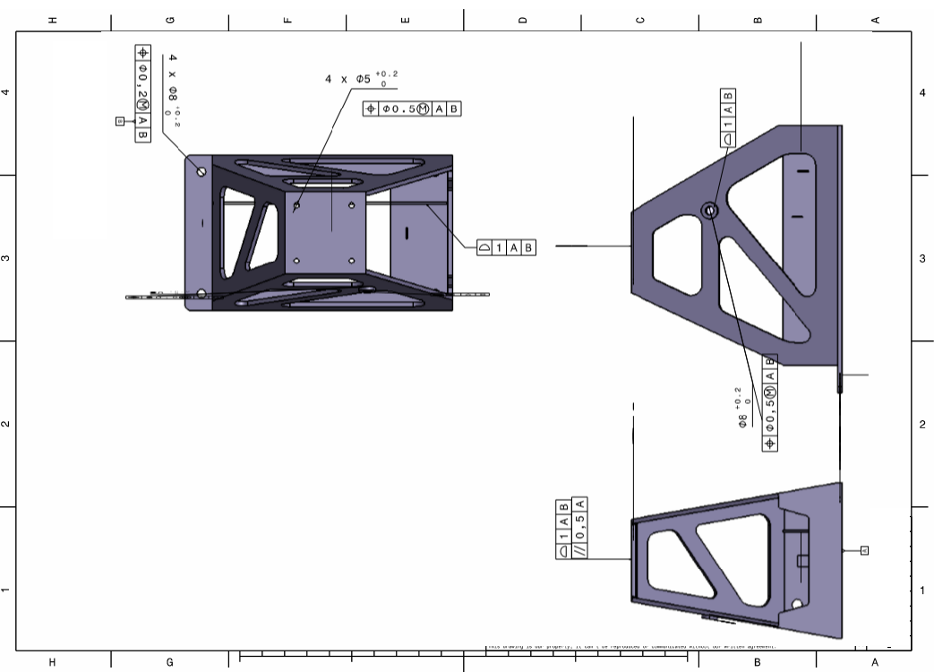
First, we need to create the datums on the Frame.
•From the Model Creation toolbar, click ![]() GD&T, then click the Frame part.
GD&T, then click the Frame part.
•The GD&T dialog will open for Frame.
•Click [Add] next to Datum Feature, you'll see the dialog shown below.
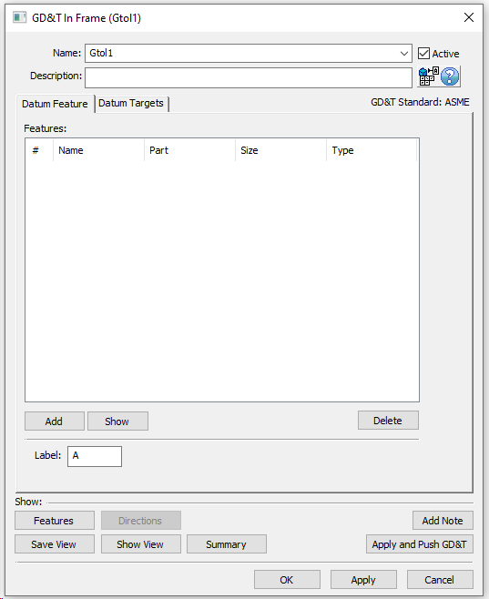
•Change the Name to "Datum A".
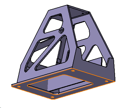
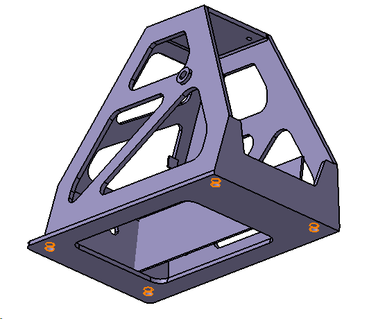
•Click [Add] and select the bottom surface of the Frame as shown in the image below.
•The completed dialog should look like the image below.
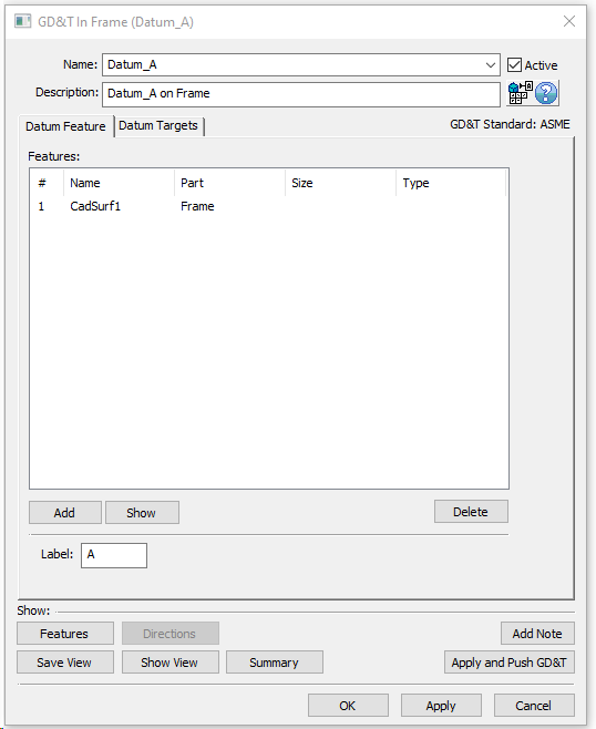
•Select [OK] to save and close the Datum A GD&T dialog.
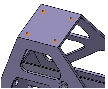
•Similarly Create "Datum B" using the 4 holes on the bottom of the Frame.
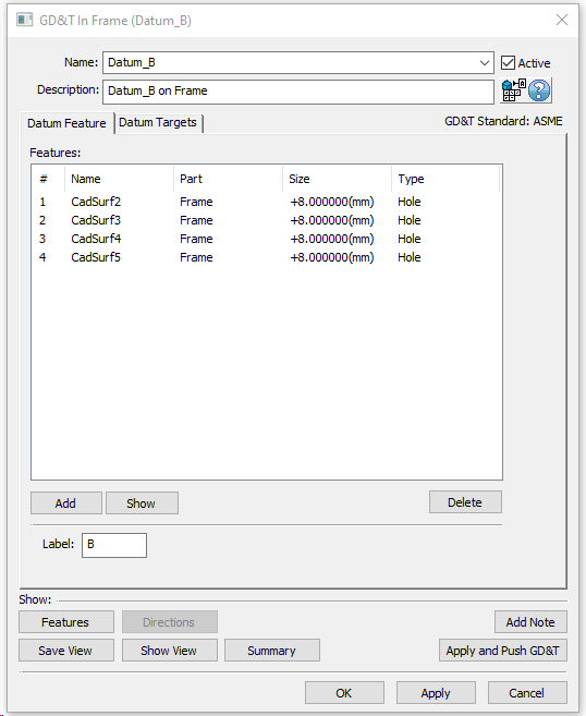
•Select [OK] to save and close the Datum B GD&T dialog.
Create the size and position on the four Datum B holes in the Frame.
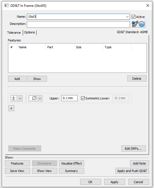
•Select Size from the GD&T dialog and click [Add]. The dialog will look like the image below.
•Rename to "Size Datum B".
•Click [Add] and select the Datum B Hole features.
•Uncheck the Symmetric Lower box. For Upper type in 0.2mm and for Lower type in 0mm.
•Click [+] to add a new frame for the selected features.
•Rename the new frame to "Position Datum B".
•In the new frame, change the type to ![]() Position from the drop down list.
Position from the drop down list.
•Select Ø diametrical for the zone type.
•Set the Range to 0.2mm.
•Select ![]() Maximum Material Condition as the material condition.
Maximum Material Condition as the material condition.
We haven't created a datum reference frame (DRF) yet so we will do that now.
•Select the [Edit DRFs...] button in the lower-right of the Tolerance tab.
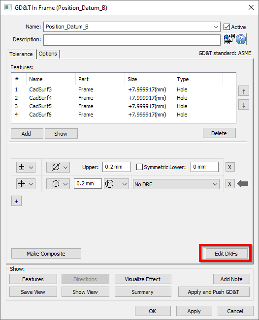
•In the Datum Features list of the Edit DRFs dialog, click Datum_A. This will add the label "A" to the first DRF field.
•Click [Add]. This will add a DRF with reference A to the Datum Reference Frames list. This can now be used in the tolerance.
•We will also add a DRF of A | B(M) to the list for future use. To do this, click the label "B" while in the Secondary box.
•Click [(M)] while in the Secondary box to add the material modifier to Datum B.
•Click [Add]. This will add a DRF with reference A | B(M) to the Datum Reference Frames list. This can now be used in the tolerance.
•Select the [OK] to return to the GD&T dialog.
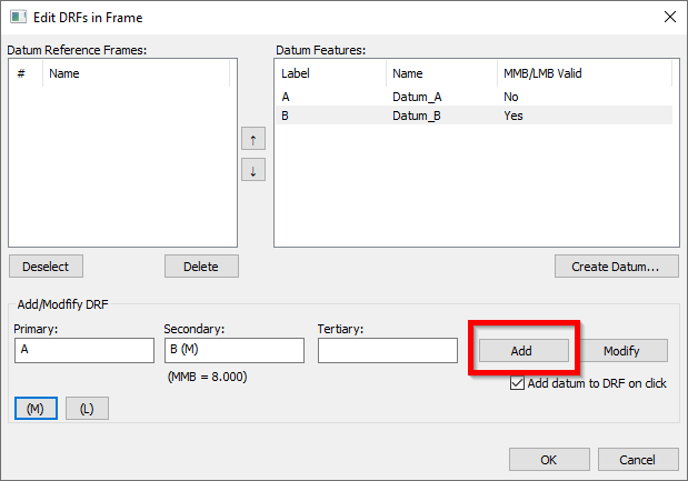
•Select A from the drop-down menu to set it as the DRF for the position tolerance. The completed dialog should look like the image below. Your CadSurf numbers may be different.
•Click [OK] to close the GD&T dialog.
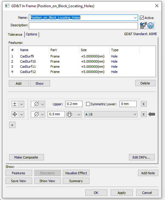
Next we have to create the size and position GD&T on the Mounting Block locating holes.
•In the GD&T dialog, select Size for the type and click [Add].
•Rename to "Size Block Locating Holes".
•Click [Add] and select the highlighted features.
•Click [Close] in the Select dialog.
•Uncheck the Symmetric Lower box and set the Upper to be 0.1mm and the Lower as 0mm.
•Click [+] to add a new frame for the selected features.
•Rename the new frame to "Position Block Locating Holes".
•In the new frame, change the type to ![]() Position from the drop down list.
Position from the drop down list.
•Select Ø diametrical for the zone type.
•Set the Range to 0.5mm.
•Select ![]() Maximum Material Condition as the material condition.
Maximum Material Condition as the material condition.
•Set the DRF to A | B(M).
•The completed dialog should look like the image below.
Now, we will add the rest of the GD&T from the Frame drawing to the 3DCS model.
•In the GD&T dialog, select Surface Profile for the type then click [Add].
•Change the Name to "Profile Frame to Stick Gap Surface".
•In the Tolerance tab, click [Add] then select the surface on Frame used for the measure "Stick and Frame Plate Min Gap" .
•Click [Close] in the Select dialog.
•Set the Range to 1mm.
•Set the DRF to A | B(M).
•The completed dialog should look like the image below.

•Click the [Options] tab in the GD&T dialog.
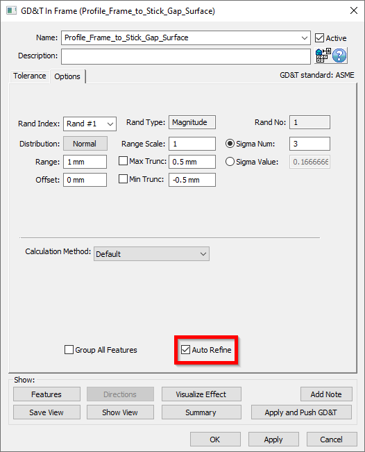
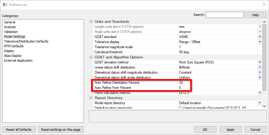
You will notice that the Auto Refine check box is checked on by default. Per the ASME standard, Surface Profile varies Location, Orientation and Form. In 3DCS, we use the Auto Refine setting to help vary all of these. With Auto Refine turned off, Surface Profile only varies Location. With it checked on, by default, Surface Profile will vary Orientation at 25% of the overall tolerance, and Form at 0%. These settings can be changed in the Preferences dialog as seen in the image below.
•Click [OK] in the GD&T dialog.
Next, create the GD&T for the Lever Assy mating hole and surface.
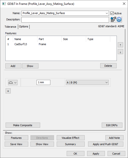
•In the GD&T dialog, select Surface Profile from the drop down then click [Add].
•Change the Name to "Profile Lever Assy Mating Surface".
•In the Tolerance tab, click [Add] then select the surface on Frame used to locate the Lever Assy.
•Click [Close] in the Select dialog.
•Set the Range to 1mm.
•Set the DRF to A | B(M).
•The completed dialog should look like the image below.
•Click [OK] in the GD&T dialog.
•In the GD&T dialog, select Size from the drop down then click [Add].
•Change the Name to "Size Lever Assy Mating Hole".
•In the Tolerance tab, click [Add] then select the hole in Frame used to locate the Lever Assy.
•Click [Close] in the Select dialog.
•Set the Upper to 0.2mm.
•Uncheck the box for Symmetric Lower and set Lower to 0mm.
•Click [+] to add a new frame.
•Change the name to "Position Lever Assy Mating Hole".
•Change the type to ![]() Position.
Position.
•Set the zone type to Ø.
•Set the Range to 0.5mm.
•Select ![]() Maximum Material Condition as the material condition.
Maximum Material Condition as the material condition.
•Select A | B(M) as the DRF.
•The completed dialog should look like the image below.
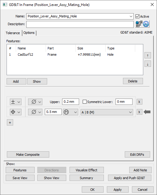
•Click [OK] in the GD&T dialog.
Next, we need to create the Profile and Parallelism on the mating surface between Frame and Mounting Block.
•In the GD&T dialog, select Surface Profile from the drop down then click [Add].
•Change the Name to "Profile Mounting Block Mating Surface".
•In the Tolerance tab, click [Add] then select the surface on Frame used to locate the Mounting Block.
•Click [Close] in the Select dialog.
•Set the Range to 1mm.
•Set the DRF to A.
•Click [+] to add a new frame.
•Change the name to "Parallelism Mounting Block Mating Surface".
•Change the type to ![]() Parallelism.
Parallelism.
•Set the zone type to blank.
•Set the Range to 0.5mm.
•Create and then select A as the DRF.
•The completed dialog should look like the image below.
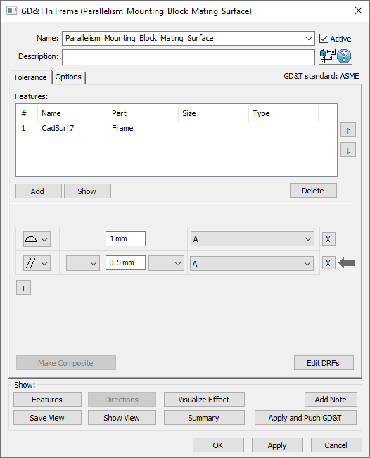
•Click [OK] in the GD&T dialog.
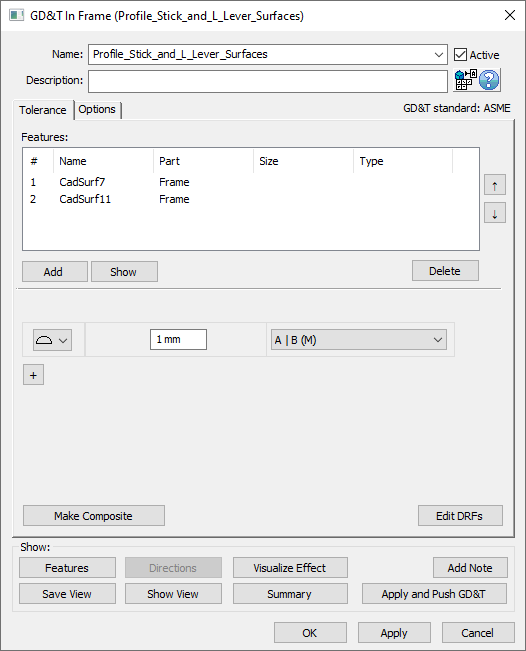
Lastly, we need to create the Profile for the remaining two floating surfaces on the Frame.
•In the GD&T dialog, select Surface Profile from the drop down then click [Add].
•Change the Name to "Profile Stick and L Lever Surfaces".
•In the Tolerance tab, click [Add] then select the surfaces on Frame highlighted below.
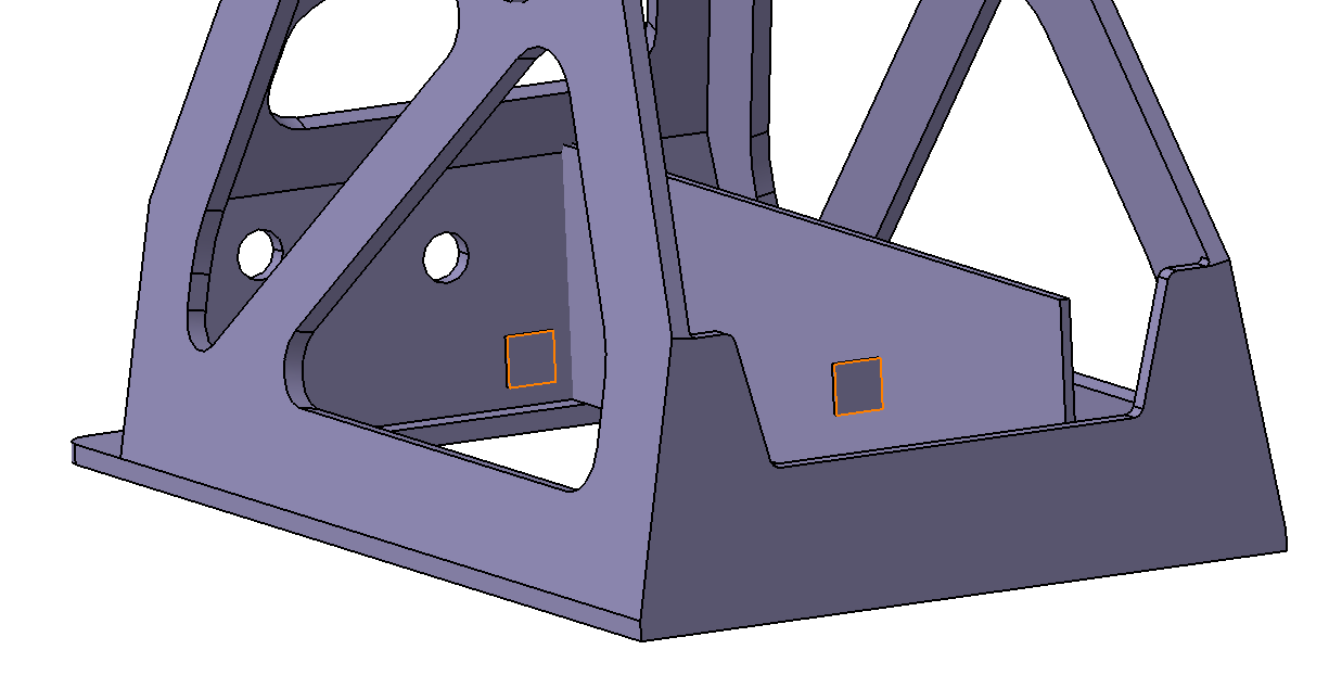
•Click [Close] in the Select dialog.
•Set the Range to 1mm.
•Set the DRF to A | B(M).
•The completed dialog should look like the image below.
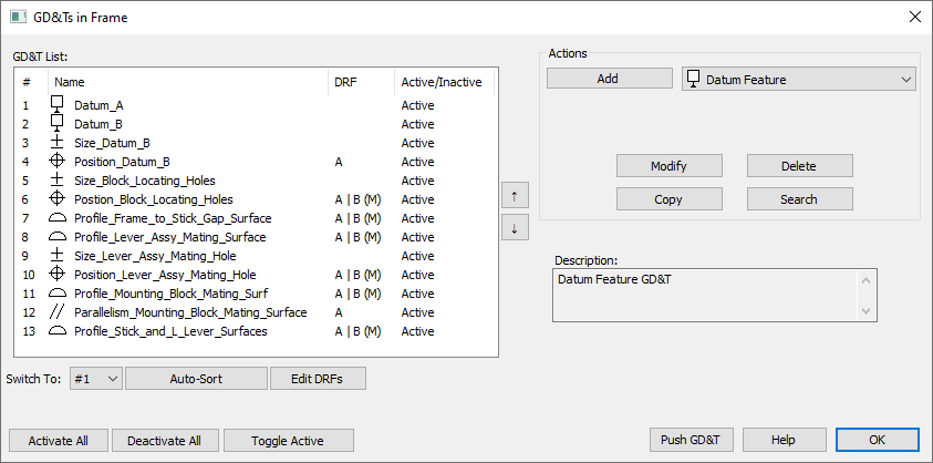
•The fully completed GD&T should look like the image below.
Review the GD&T
•If the mesh is off, click ![]() Show Mesh to turn the mesh on.
Show Mesh to turn the mesh on.
•Click ![]() Deviate to show the variation of the tolerances just created.
Deviate to show the variation of the tolerances just created.
•Click ![]() Nominal Build.
Nominal Build.
• Again ![]() Deviate to see the model deviating for the applied tolerances and moves.
Deviate to see the model deviating for the applied tolerances and moves.
•Save the model.