A location Dimension creates a size between two features in a direction. The tolerance allows the non-origin feature to change within a specified range. Here's a step-by-step process to create a linear tolerance in Solidworks.
|
Procedure:
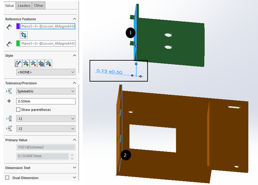
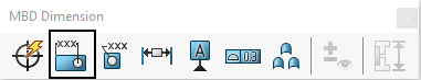
1.Select the Location Dimension in the MBD Dimension toolbar.
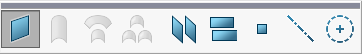
2. The feature-type toolbar will appear. Select two features in a part or an assembly to define a Location tolerance/dimension.
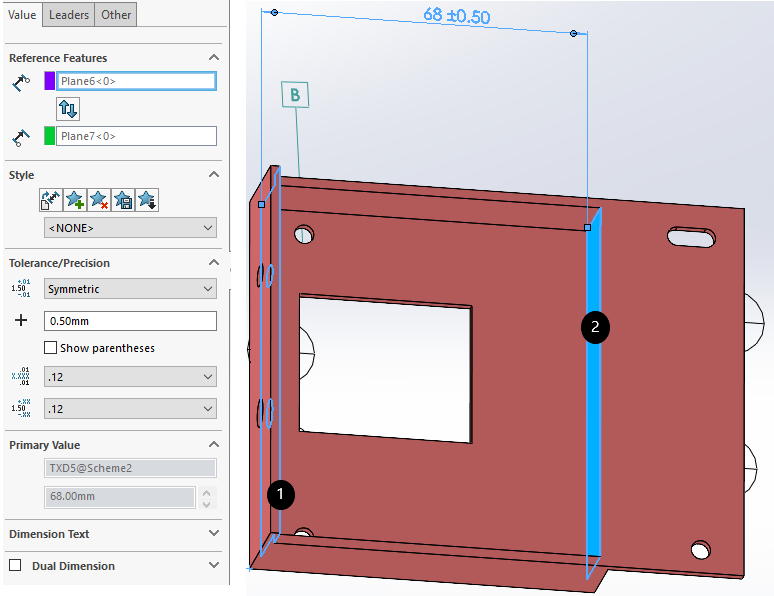
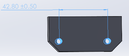
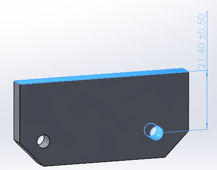
3. Two Planar Surface or two cylindrical features or combination of both can be selected to define the Location Dimension.
4. Once finished, left-click in space.
5. One the left DimXPert pane, change the tolerance range and type to be created.
This GD&T will now be extracted as Dimensioning Location in 3DCS and will automatically assign the origin to the first feature in the list.
.
|
|
|
|