I. Overview
The 3DCS FEA Compliant Modeler (3DCS FEA CM) is an add-on module to 3DCS which utilizes Finite Element Methods to accurately simulate variation of compliant parts and assemblies. 3DCS FEA Compliant Modeler simulates compliant parts deformation resulting from manufacturing operations such as clamping, joining, unclamping, forces, and temperature change application. 3DCS FEA CM deforms the parts during simulation based on the material properties (Young's Modulus, Poisson's Ratio, density, and expansion coefficient) for each compliant part identified within the 3DCS model. The mesh file is acquired from FEM/FEA software.
Below are the general steps necessary in creating a compliant 3DCS model:
1. Rigid Body Model - create a completed 3DCS model utilizing the standard DCS Moves, Measures and Tolerances. This is called a rigid model. The compliant model will be built on top of the rigid model.
2. Compliant points - determine which parts in the rigid model will be simulated as compliant (flexible) parts. On these compliant parts create additional points for the clamp, join, force application locations (some of these points may already be created for the rigid model). Create any additional modeling points in locations on compliant parts where visual bending is desired and additional points where measurements will be taken.
3. Mesh files - Using an FEA meshing software, create a mesh file for each of the compliant parts. To increase accuracy the user should create a finer mesh with higher-order elements (such as quadratic rather than linear).
4. Create FEA files - If available, select the FEA Solver in the StiffGen dialog. The solver will be an executable file such as abq6141.exe, or Nastran.exe. StiffGen can call the solver using a *.bat file as well. This will allow you to generate the stiffness, mass, load, or thermal files from inside the 3DCS software. Also it will automatically create an updated mesh file that contains a list of ASETs (closest mesh nodes to the modeling points).
5. Load FEA files - create the Load FEA Data move(s) and load the mesh, stiffness, mass files. Once loaded a Nominal Build is required to link the ASETs in the mesh file to the modeling points for all parts.
6. Constrain the parts - This is a case specific operation based on the build sequence. Parts can be fixed in space with LockDOF, clamped to a fixture or clamped to another part. It is important that parts are fully constrained at all steps of the build sequence. Users can combine hard and soft clamps in the same move if they consider necessary. The clamps can be sequenced inside the move. A best practice is to use three hard clamps at the primary direction locators (datums if applicable) and use soft clamps at the other locations.
7. Create the other compliant moves: gravity, join, force application, thermal. All these moves should be applied on fully constrained parts.
8. Second stage - To relocate the part(s) to the second stage fixture (or another part), follow these steps:
8.1. UnLock all locked points. Unclamp the parts from the first fixture but keep clamped up to three points. These (three) points should be later used to clamp the part in the next stage (if applicable). The assembly will relax (springback) relative to these unclamped points. For a 3-DOF stiffness matrix three points that form a plane are necessary to fully constrain the part with a hard clamp. For a 6-DOF stiffness matrix a single point can be clamped with a hard clamp to fully constrain the part. User should pay attention when unclamping so the part does not become underconstrained.
8.2. Unclamp the last points using the Skip Deformation. This option will unclamp the points without deforming the parts. The part/assembly (already relaxed relative to these last clamped points), will keep the shape until it is clamped in the next stage.
8.3. Use a rigid body move to transfer the part(s) to the new location (fixture).
8.4. Clamp the part(s) to the second fixture (or target part).
8.5. Create the other compliant moves for this level.
Tips for improving the performance of the compliant model:
1. Break down the assembly into smaller subassemblies to be modeled as compliant whenever possible. Then follow the 'black-box' method to model the compliant subassemblies as parts into the final assembly. At each subassembly level the variation will be determined based on the individual part variation (tolerances and part deformation due to compliant moves). That subassembly will then be included in the final assembly as one part with it's variation previously calculated and with its own mesh file (this will be an assembly mesh file).
2. Generate stiffness matrix in the assembly orientation. Although CM supports rotating parts, this requires a transformation of matrix to adjust the orientation of the stiffness matrix, which adds computational cost. If stiffness matrix is set up in the design orientation, the calculation triggered by transforming stiffness matrix can be omitted.
3. Delete unused modeling points. Reducing modeling points number will make stiffness and mass matrix smaller.
4. Soft clamp is computationally more intensive compared with LockDOF and hard clamp. Soft clamp is applied by adding extra constraints to the stiffness matrix, while LockDOF and hard clamp are applied by constraining existing DOFs.
Prerequisites
•User: Working knowledge of 3DCS Variation Analyst Software
•Software: 3DCS Variation Analyst Version 6.3.7 or greater, 3DCS FEA Compliant Module License, Completed Rigid Body 3DCS Analysis Model, Stiffness, Mass, Load Matrices and Mesh files for all parts deemed Compliant. Access to an FEA software package is preferred.
Assumptions and Limitations
•All modeling points that are to be used in the model are already created on every compliant part in the model. Ideally, the rigid body model is complete.
•One Finite Element Mesh and Stiffness Matrix per part.
•Every modeling point in the compliant part should be associated to an FEA mesh point, otherwise it will deviate (if toleranced directly or through an associated feature), but deformation will be approximated through Smoothing.
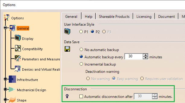
Settings
•Compliant models may take a long time to run the Analysis. Please deactivate this setting:
Outputs
The analytical output will include Monte Carlo, HLM, GeoFactor consistent with the current 3DCS Variation Analyst based capability. The analytical output reports and analysis files will be consistent with the current 3DCS Variation Analyst based capability.
Model Files
The files required for the completion of this tutorial can be found on the following default directories:
C:\Users\Public\Documents\DCS\3DCS_V5_8_2_0_0\Tutorials\V5_CM_Tutorial