Introduction
Welcome to the 3DCS Variation Analyst Tutorial. This tutorial will take you through the basics of creating a model in 3DCS integrated with 3DEXPERIENCE integrated with CATIA V5 integrated with Creo integrated with SW integrated with NX. In this tutorial, the terms "3DCS Variation Analyst" and "3DCS" are used interchangeably.
3DCS is designed to perform dimensional analysis of an assembly of parts. A part is defined by its geometry (dimensions) and material properties. When manufacturing the part, the dimensions will vary since no process is capable of making perfect parts. The allowable amount of variation of a part is specified with tolerances. Dimensional analysis uses the part tolerances as well as assembly process to predict the variation of the overall assembly.
The goal of dimensional management is to minimize the overall cost of producing the designed assembly while maintaining an acceptable amount of variation.
Variation modeling is a key component within dimensional management. Variation modeling is a technique where a designer or an engineer creates a model to mathematically simulate and calculate the amount of dimensional variation expected for an assembly. Variation modeling quantifies the overall dimensional management plan, and is used to test new ideas, so that as the overall plan is refined, the best solutions are found.
Inputs Required for Variation Modeling:
Part Geometry: The shape of the parts affect how variation is passed from one level of the assembly to the next. Part tolerances may be amplified or mitigated depending on the features used to locate parts. Ideally, the modeling process should be started before the geometry is finalized so that modifications can be made, if necessary, with minimal impact on the program. 3DCS represents part geometry with both Features and Points.
Part Variation: Variation must be added to the nominal CAD part geometry to represent variation inherent in manufacturing real-world parts. In 3DCS, a user can apply Geometric Dimensioning and Tolerancing (GD&T) to the CAD. GD&T follows the tolerancing standards from ASME or ISO rules. 3DCS can help to determine the largest possible part tolerances while still meeting the variation requirements of the assembly. This means parts can be produced at the lowest possible cost.
Assembly Process: To have the most accurate model possible, it should follow the same real-world process that is used to assemble the parts. The order in which parts are assembled, the features that are used to located the parts, and the use of fixtures all contribute to the variation of the final assembly. 3DCS uses Moves to represent the assembly process. Moves define how parts are located and the order of the Moves defines the order that the parts are assembled.
This tutorial will use point-based moves. Point-based moves are more accurate for complex part geometries compared to the Feature Move. The Feature Move is good for parts with simple geometries. For more information on the Feature Move, please see the 3DCS Feature-Based Tutorial or the 3DCS Help Manual.
Measures: How good does a product have to be to work? What will it take for the product to be assembled? How will the product be evaluated such that good and bad parts can be separated? Product requirements define which features will have their variation tracked and the allowable amount of variation. In 3DCS, Measures track and output these requirements.
The 3DCS model needs all four of these inputs in order to generate analysis results. The inputs can be added to the 3DCS model in any order. The important thing is that the model mimics the real-world assembly as closely as possible in order to provide meaningful results.
Outputs from Variation Modeling
Monte Carlo Simulation: Monte Carlo Simulation reports the variation and other statistics of the assembly. Monte Carlo Simulation does not statistically stack the tolerances but simulates virtual builds of the assembly. For each Monte Carlo Simulation run, the parts are deviated according to the specified tolerance ranges and distributions. Then the deviated parts are assembled according to the Moves. This produces one sample build which gets measured. This process is repeated for the specified number of runs. This produces a large number of samples from which the statistics are calculated.
GeoFactor Analysis: Calculates the Statistics for the measurement from the Contributor Analysis results.
The Contributor Analysis calculates the effect of each tolerance on a measurement. It calculates the tolerance contribution based on geometric effect, tolerance's range, bonus tolerance and Distribution of Range.
To quantify the geometric effect, GeoFactor provides a GeoFactor value for each contributor. If a contributor has a GeoFactor with an absolute value less than 1, then the variation of the contributor is mitigated by the part geometry at the measurement location. If a contributor has a GeoFactor with an absolute value greater than 1, then the variation of the contributor is amplified by the part geometry at the measurement location. Basically, the GeoFactor number is the scalar of each contributor on the measurement.
Move, Tolerance, Measurement (MTM) Location in the Navigation Tree
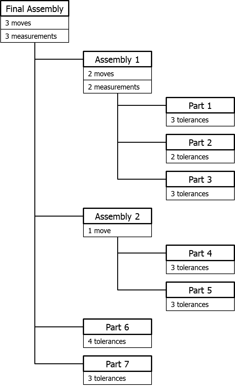
When creating a model in 3DCS, the Moves, Tolerances, and Measures (MTM) can be created in any order. When the software runs the Monte Carlo Simulation, it will apply the Tolerances first, then the Moves, then the Measures within a parent component. The order of execution begins with the lowest order child component in the tree and works up to the highest parent component.
To get the correct analysis results, the user needs to take into account the following:
•Moves should always be at least one level above the parts or assemblies used in the Move. This is to ensure Tolerances are executed in the software before the Moves and the variation stacks up.
•Tolerances are generally applied at the part level. If multiple parts are being treated as a black box (single component), or a subassembly with no Moves (the parts in the subassembly are treated as one), then the Tolerances can be applied at the subassembly level.
•Measures should be at least one level above the parts or assemblies that contribute to the variation of the Measure. Generally, they are applied at the final assembly level (the highest parent). Measures will only track the variation up to the level they are applied to. If a Measure is applied at the part level, it will only track the detail part Tolerances. If a Measure is applied at a subassembly level, it will only track the variation within that subassembly. If a Measure is applied at the final assembly level, it will track all of the part Tolerances plus the assembly variation caused by all of the Moves.
Below is a Navigation Tree illustrating the typical placement of MTMs.