•Go to File ![]() Save Management.
Save Management.
•Select the Lesson_4 Manual Gear Shifter Asm.CATProduct and select [Save As...].
•Navigate to a New folder and rename to "Lesson5" that will be easily accessible later.
•Click [Propagate Directory] to save a copy of the CATPart files to the new folder.
•In the Save As dialog, rename the Product to "Lesson_5 Manual Gear shifter Asm" and click [Save].
•In the Save Management dialog select [OK] to save the CATIA Product under its new name. The model is not saved until you click OK.
•Go to [File] ![]() [Save As].
[Save As].
•In the Save a Copy dialog, enter "Lesson_5 Manual Gear shifter Asm." for the File Name, make sure the Type is set to Assembly (*.asm), then click [OK].
•In the Assembly Save a Copy dialog, click [Save Copy and Open] to save the assembly under its new name, and open the newly saved assembly.
•Close the 3DCS Model Navigator and Creo window for Lesson_4 Manual Gear shifter Asm.
•Click ![]() Update Model in the new window for Lesson_5 Manual Gear shifter Asm.
Update Model in the new window for Lesson_5 Manual Gear shifter Asm.
•Go to [File] ![]() [Save As].
[Save As].
•In the Save As dialog, enter "Lesson_5 Manual Gear shifter Asm" as the new File name and make sure the type is set to Part Files (*.prt).
•Click [OK] in the Save As dialog.
•Click ![]() Update Model.
Update Model.
•Go to [File] → [Save As].
•In the Save as dialog, enter "Lesson_5 Manual Gear shifter Asm" for the File Name, and make sure the Type is set to Assembly (*.asm).
•In the Assembly Save as dialog, click [Save Copy and Open] in the bottom left of the dialog to save the assembly under its new name, and open the newly saved assembly.
•Click Update Model in the new window for Lesson_5 Manual Gear shifter Asm.
•Click the ![]() Application Button then select
Application Button then select ![]() Save As.
Save As.
•Change the File Name to "Lesson_5 Manual Gear Shifter Asm"and make sure the Type is set to WTX DATA(*.wtx)
•Click [Save] in the Save As dialog.
For any model it is good practice to start the subassembly moves/constraints first followed by main assembly.
Pivot Sub-Assembly
This section will focus on creating constraints for the Pivot Assy first.
•Click ![]() Moves in the Model Creation toolbar to create moves and the select Pivot Assy from the tree.
Moves in the Model Creation toolbar to create moves and the select Pivot Assy from the tree.
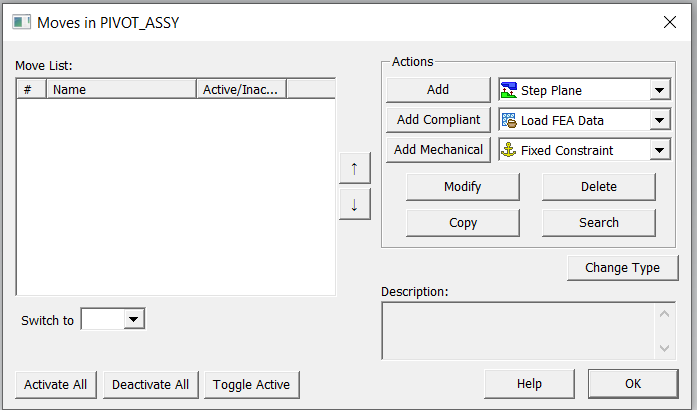
•Make sure the sub assembly name is displayed correctly at the top left corner and then proceed to add the constraints to the sub assembly.
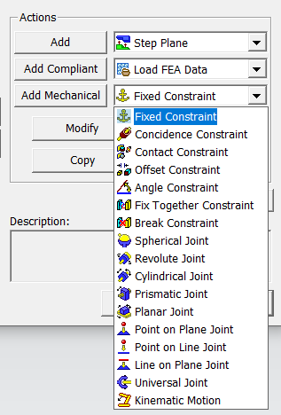
•Select Coincidence Constraint from the drop down menu and click [Add Mechanical].
•Name the constraint "Axis Select Pin to Pivot".
•Click [+] to add a feature into the Object Features list.
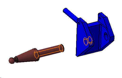
•Add the Pin Surface on the Select Pin.
•Click [Close] in the Select dialog.
•Click [+] to add the hole in the Pivot to the Target Features list.
•Click [Close] in the Select dialog.
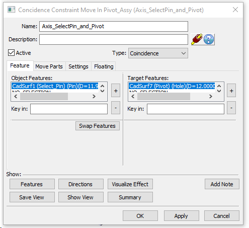
•Click the Settings tab and change the Allow Drop DOF setting to Yes. This will need to be done for all Coincidence Constraints that will be created in the model.
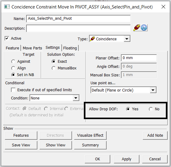
•Click [OK] to create the move.
•From the Moves dialog select Contact Constraint from the drop down list and click [Add Mechanical].
•Rename the constraint “Surface Contact Select Pin to Pivot”. Select the surfaces under object and target list as shown below.
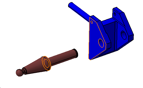
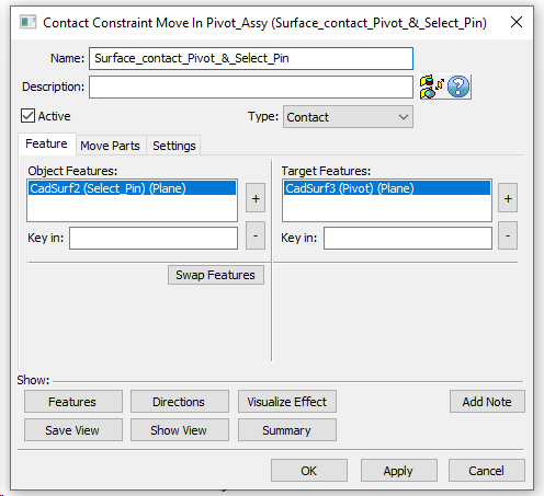
•Click [OK] to create the move.
It is a best practice to create a Fix Together Constraint for the sub assembly parts as the last move, which improves the analysis speed. This is an optional move but is added below.
•From the move list select Fix Together Constraint and click [Add Mechanical]
•Rename the Constraint "Fix Together Select Pin and Pivot"
•[Add] Select Pin and Pivot by clicking on them in the graphics window.
•Click [Close] in the select dialog.
•The completed dialog should look like the image below.
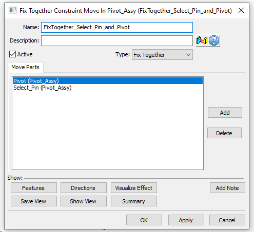
•Click [OK] to create the move.
•Click [OK] to close the Moves dialog
•Click ![]() Nominal Build to see the parts build using the constraints.
Nominal Build to see the parts build using the constraints.
•Click ![]() Separate.
Separate.
•Click ![]() Animate and step through each move.
Animate and step through each move.
Lever Assembly
•Click ![]() Moves then click Lever Assy from the tree to start creating moves for the Lever Assy.
Moves then click Lever Assy from the tree to start creating moves for the Lever Assy.
•Follow the steps above to create a Coincident Constraint and Contact Constraint between the Lever Pin and the L Lever. Finish the Lever Assy constraints with a Fix Together Constraint.
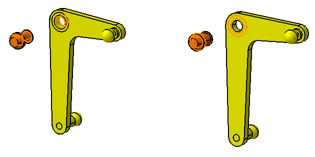
•Use the features seen below for the Coincident Constraint and Contact Constraint, respectively. Be sure to set the Allow Drop DOF setting to Yes in the Coincident Constraint.
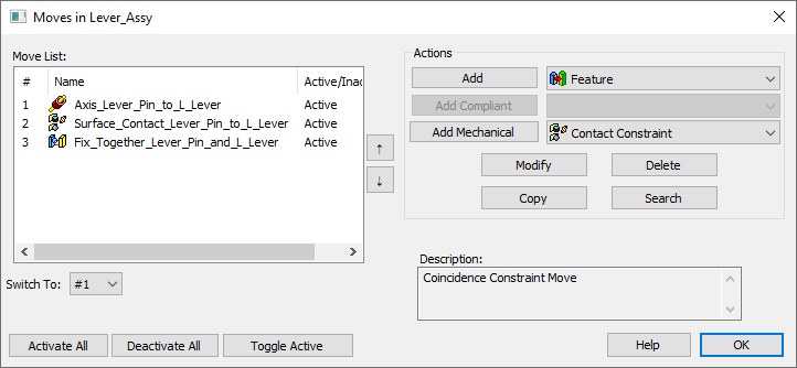
•The completed moves list should look like the image below.
•Click ![]() Nominal Build. The two sub assemblies should build together.
Nominal Build. The two sub assemblies should build together.
•Click ![]() Separate.
Separate.
•Click ![]() Animate and step through each move.
Animate and step through each move.
Creating Main Assembly Constraints
•Click ![]() Moves from the toolbar and select the top product to open the Move dialog.
Moves from the toolbar and select the top product to open the Move dialog.
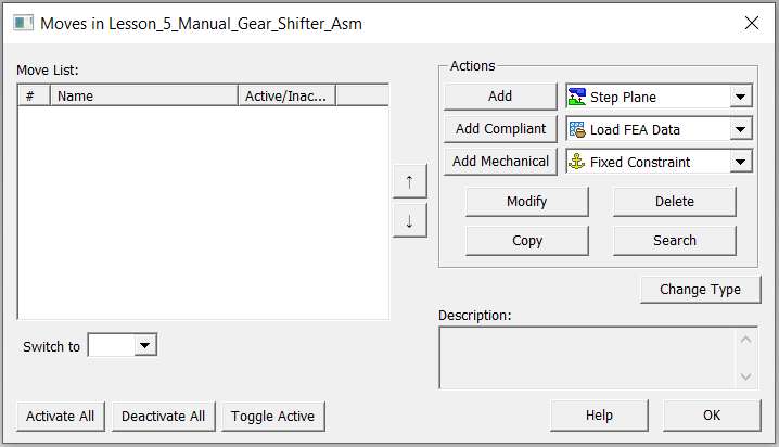
•Select Fixed Constraint from the Move list and click [Add Mechanical].
•This will open the Fixed Constraint dialog.
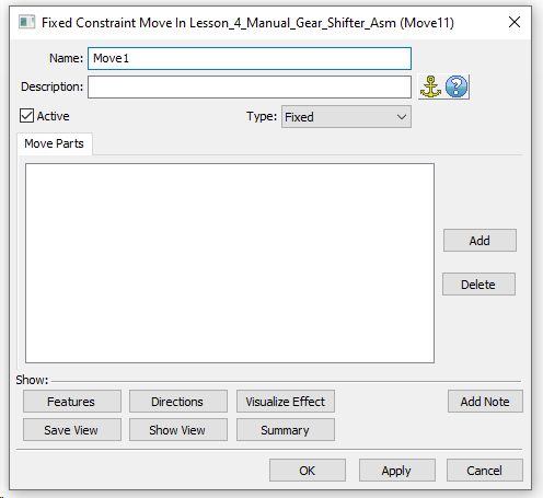
•Name the Move "Fix Frame".
•Click [Add] and select the Frame from the Graphics. Click [Close] in the Select dialog.
•The completed Fixed Constraint should look like the image below.
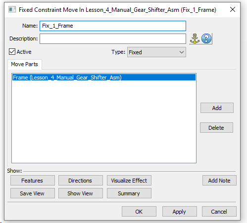
•Click [OK] to save and close the Fixed Constraint.
Move Mounting Block to Frame
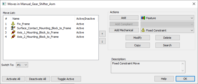
•The Mounting Block can be fully constrained to the Frame with 3 more Constraints.
•Create one Contact Constraint and two Coincident Constraints using the features highlighted in the images below.
•Change the Allow Drop DOF setting to Yes for all Coincidence Constraints.
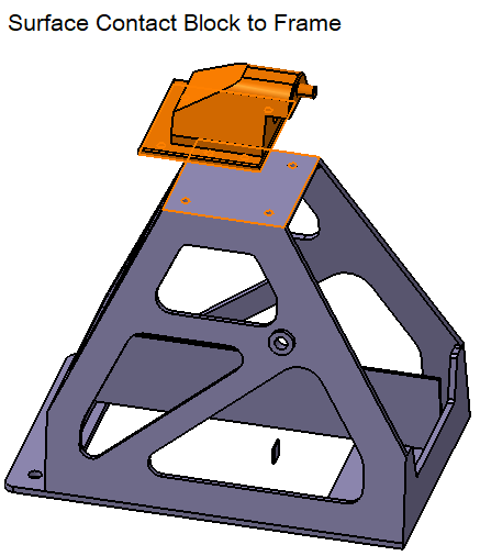
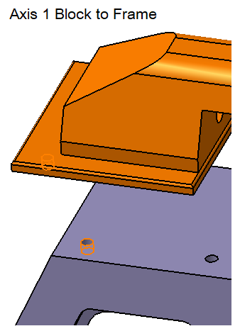
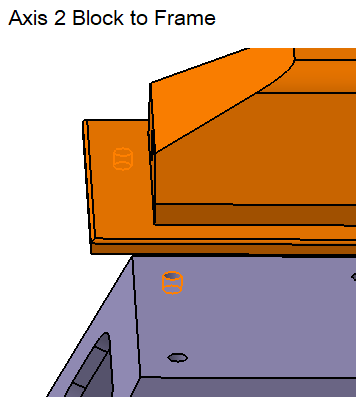
•The completed Move dialog should look like the image below.
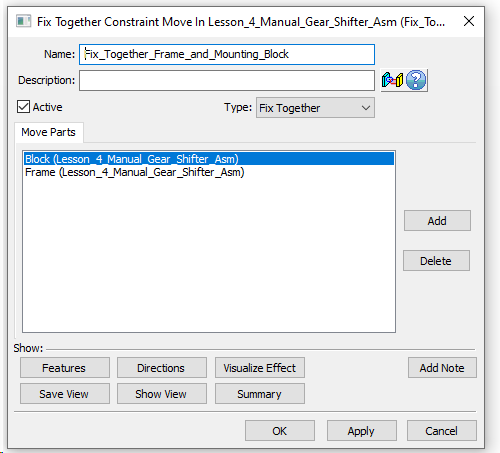
•After assembling the Mounting Block to the Frame, create a Fix Together Constraint for the two parts.
Moving Pivot Assembly to Mounting Block
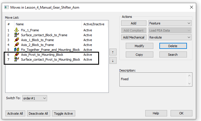
•The Pivot Assy can be fully constrained to the Mounting Block with 2 more Constraints.
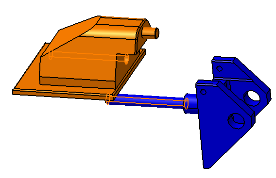
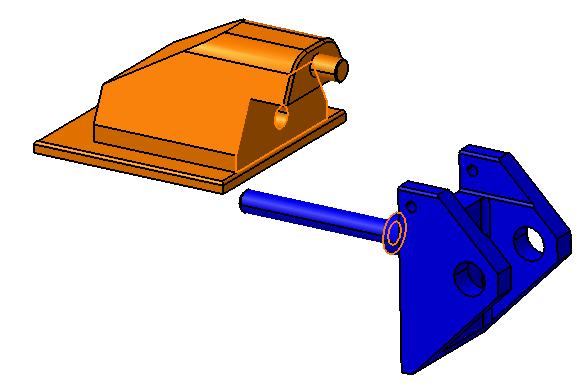
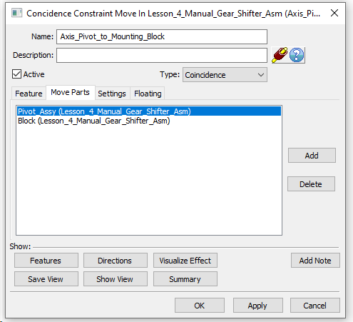
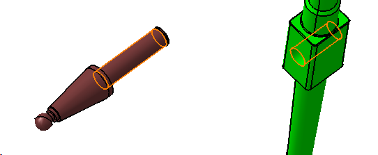
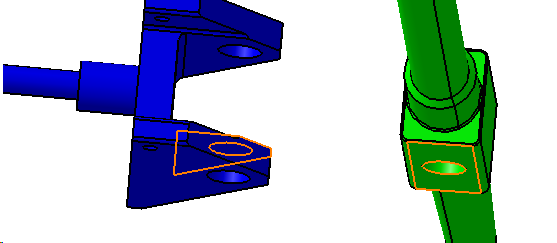
•Create one Coincident Constraint and one Contact Constraint using the features highlighted in the images below. Be sure to change the Allow Drop DOF setting to Yes for Coincident Constraints.
•Notice that selecting features from the Pivot will add the Pivot Assy in the Move Part list which will move the whole assembly to the Mounting Block.
Moving Stick to Pivot Assembly and Frame
•The Stick can be fully constrained to the Pivot Assy and Frame with 3 more Constraints.
•Create one Coincident Constraint and two Offset Constraints using the features highlighted in the images below.
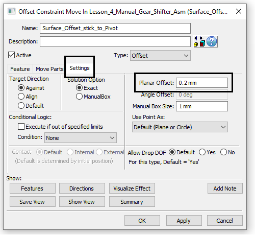
•The Offset Constraint between the Stick and Pivot will utilize an offset of 0.2mm between the features shown below.
•The offset value can be set in the Settings tab of the Offset Constraint dialog.
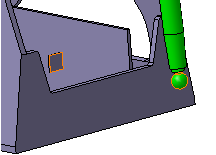
•Complete the Offset Constraint for the Stick to Frame with an offset value of 5mm using the features in the image below.
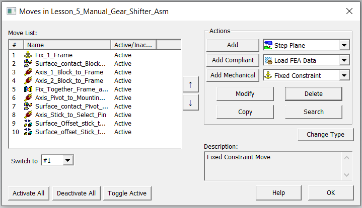
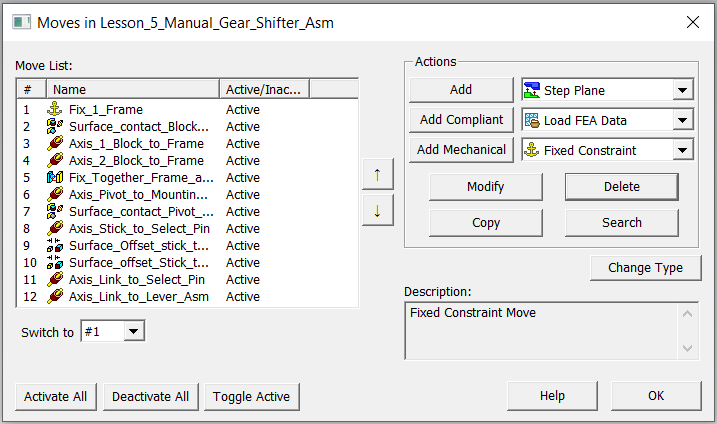
•Up to this point, the completed list of moves should look like the image below.
Moving Link to Pivot Assembly and Lever Assembly
•The Link can be fully constrained to the Select Pin and Lever Assy with 2 Constraints.
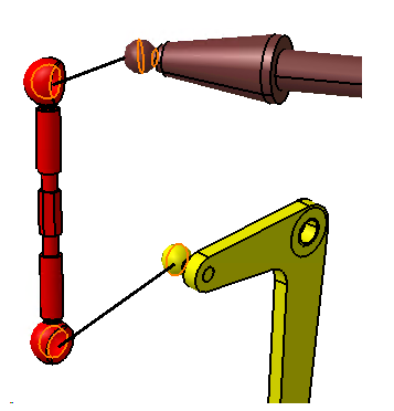
•Create two Coincident Constraint using the features highlighted in the image below.
•Based on the geometry of these features, we will turn the float off for both of the Coincident Constraints. These are meant to be snap features with no float available. This can be done in the Floating tab.
•Up to this point, the completed list of moves should look like the image below.
Move Lever Assembly to Frame
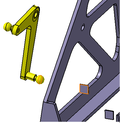
•The Lever Assy can be fully constrained to the Select Pin and Lever Assy with 2 more Constraints.
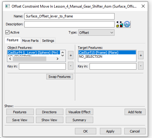
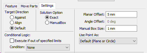
•Create one Offset Constraint using the features highlighted in the image below with an offset of 5mm.
•Next add a ![]() Revolute Joint. The Revolute Joint will allow an axis and a plane to be constrained in one move.
Revolute Joint. The Revolute Joint will allow an axis and a plane to be constrained in one move.
•Select Revolute Joint from the move list and click [Add Mechanical].
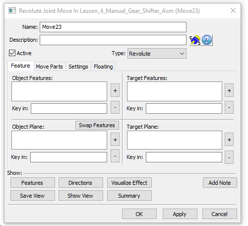
•Rename the move to "Revolute Lever Assy to Frame"
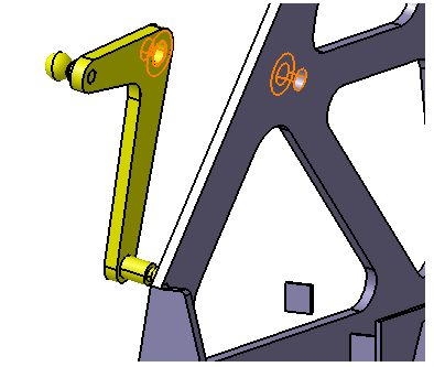
•Select the highlighted hole from Lever Assy and the hole from Frame.
•Similarly select the highlighted planes from Lever Assy and then Frame.
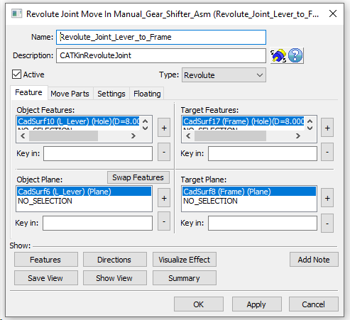
•Click [OK] to save and close the Revolute Joint dialog.
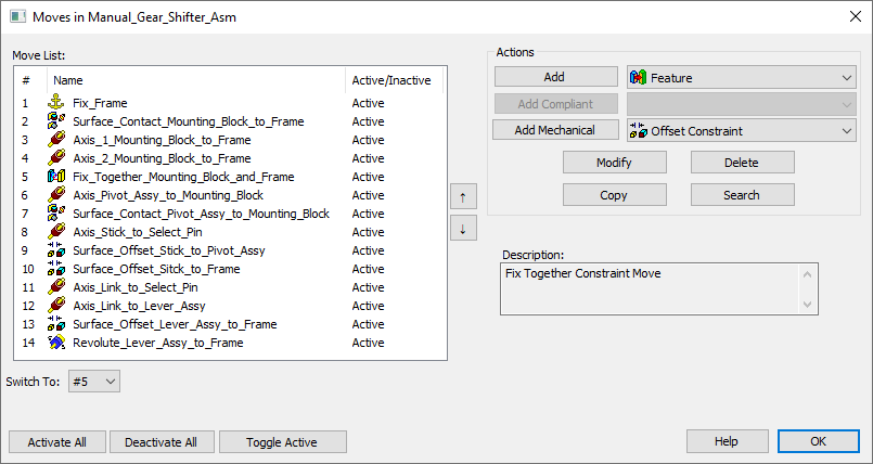
•The completed move dialog should look like the image below.
•Click ![]() Nominal Build to see the parts build using the moves.
Nominal Build to see the parts build using the moves.
•Click ![]() Separate.
Separate.
•Click ![]() Animate and step through each move.
Animate and step through each move.
•Save the model.