The Kinematic Motion move works in conjunction with the Kinematic Animation and Kinematic Simulation routines. Kinematic Motion moves rotate or translate a part while maintaining joints and constraints. This allows the assembly to be analyzed at various positions. The Kinematic Animation graphically animates the selected kinematic motion move. The Kinematic Simulation function repeats the tolerance analysis at each step of the kinematic motion move.
![]() Kinematic Motion.
Kinematic Motion.
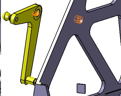
•Create a Kinematic Motion move about the Lever assembly, to allow it to rotate about its hole axis.
•On the DCS Mechanical toolbar, select ![]() Kinematic Motion.
Kinematic Motion.
•Select the top product, 3DCS_Manual_Gear Shifter, in the Navigation Tree.
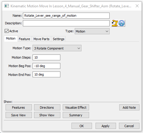
•Name the move "Rotate_Lever_See_range_of_motion" .
•Under the Motion tab, change the Motion Type to Rotate Comp, the Motion Steps to 10, the Motion Beg Pos to -10deg, and the Motion End Pos to 10deg.
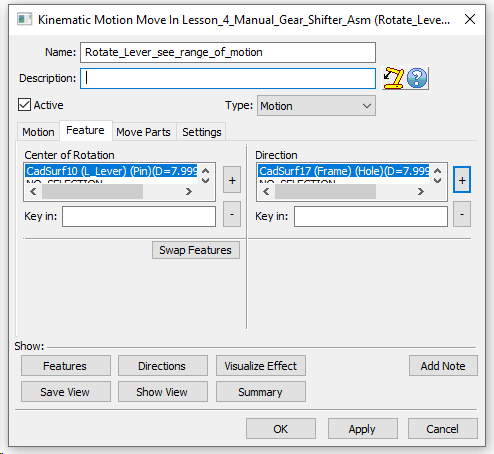
•Under the Feature tab, select the Lever hole for the Center of Rotation and select on frame Hole for the Direction.
•Deactivate the move by un-checking the box at top left.
•Click [OK] to create the kinematic move.
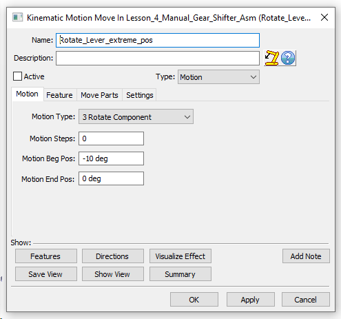
•Add other motion move, with same features as above but rename as "Rotate_Lever_extreme_position".
•Under the Motion tab, change the Motion Type to Rotate Comp, the Motion Steps to 0, the Motion Beg Pos to -10deg, and the Motion End Pos to 0deg. This will build at extreme position as nominal build and user can do deviation analysis at that position.
•Deactivate the move by unchecking the box at top left.
•The Move Parts tab should list just the lever assembly and Frame.
•Click [OK] to create the kinematic move.
•To view the range of motion (mechanism), activate the first motion move “Rotate_Lever_See_range_of_motion” by right click the Move from the tree and select ![]() Activate/Deactivate.
Activate/Deactivate.
•Deactivate the “Offset_Lever_Asm_to_Frame” move to avoid over constraining the model.
•To test the motion, click on ![]() Nominal Build and
Nominal Build and ![]() Deviate. The Lever should rotate and Stick should oscillate from its mean. Click [Close].
Deviate. The Lever should rotate and Stick should oscillate from its mean. Click [Close].
Motion moves should generally be placed immediately following the move that restricts the rest of their DoFs. In this model, motion move is right after Revolute joint.
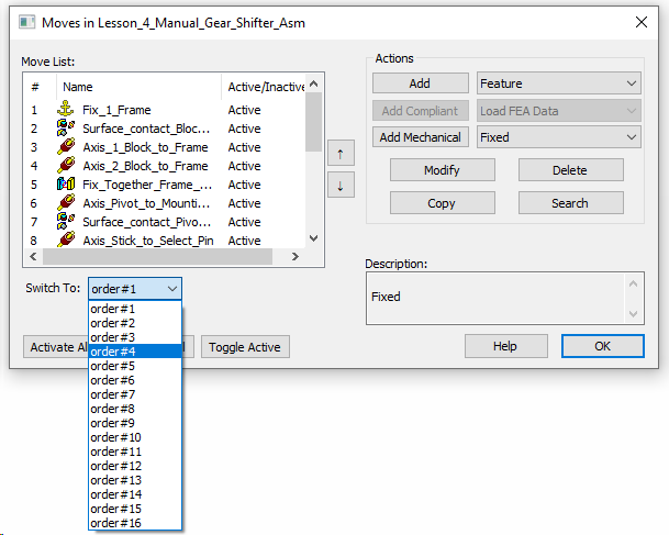
•If user want to navigate the moves to change the sequence of moves. Double click on moves icon under DCS main tree to open the Moves List dialog. Select the move to change the order, select the move number from switch To drop down list and select the number [#]. This will move the Move to desired location.
•Click on ![]() Kinematic Animation to observe the motion of the Gear Shifter step by step. Make sure the First motion move is Active.
Kinematic Animation to observe the motion of the Gear Shifter step by step. Make sure the First motion move is Active.


•The dropdown menu lists all available motion moves. In this case, Motion_Gear Shifter is the only option.
•Use the (![]() or
or ![]() ) Single Arrows to scroll through individual steps one by one.
) Single Arrows to scroll through individual steps one by one.
•Use the (![]() or
or ![]() ) Ending Arrows to observe the model running through all steps. The
) Ending Arrows to observe the model running through all steps. The ![]() Hold/Pause button will stop the animation from running at any point.
Hold/Pause button will stop the animation from running at any point.
•Click [Close] to exit the animation.
•Save the Model.