Whenever you create a new model, it is important to get the tree structure set up correctly. The model tree establishes the sequence that Moves, Tolerances, and Measurements (MTMs) are applied during the simulation so the model tree should be set up to mimic the real-world assembly process. For example, if several parts are built up in a rigid sub-assembly before going to the final assembly, the model tree should contain a branch for that sub-assembly. Rearranging the tree in the middle of modeling is difficult and can cause data loss if done incorrectly. Note that the model performs Tolerances first, then Moves, then Measures in each part starting at the lowest level in the tree. 3DCS can only "see down" the tree, i.e. an MTM can only reference parts within its branch of the tree. MTMs at the top level can reference all the parts in the model.
You open the Catia File from the directory C:\Users\Public\Public Documents\DCS\3DCS_V5_8_2_0_0\Tutorials\Catia V6 MVM tutorial \User Lessons\Product.Catproduct.
•Right-click the new product, Product1, from the Navigation Tree and select Properties.
•In the Product tab, change the Part Number to "Lesson_3 Manual Gear Shifter Asm".
•Click [OK].
In 3DEXPERIENCE, 3DCS needs to use either a Mechanical and Kinematic Simulation to hold and save the 3DCS data with the model.
•Highlight the ![]() Insert icon and select Content... The New Content dialog will appear.
Insert icon and select Content... The New Content dialog will appear.
•In the New Content dialog select Manufacturing Simulation (in Simulation Meta-Modeler).
•Right-click on the new Manufacturing Simulation in the model tree and select Properties.
•In the Reference tab of the Properties dialog, change the Title to "Lesson_3 Manual Gear Shifter Asm".
•In the Compass, go to the South Quadrant (labeled V+R) and select 3DCS Variation Analyst V6 in the V+R My Simulation Apps section. This will change the workbench to 3DCS Variation Analyst.
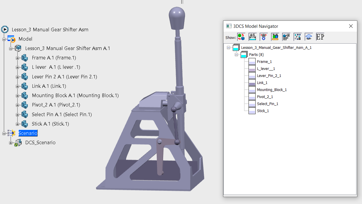
The Navigation Tree and Graphics Window should now look like the following image for Lesson_3 Manual Gear Shifter Asm
The first thing we will do is create a CATProduct and insert the parts. If you already have a CATProduct of your assembly, you can use that for the 3DCS model. We will start from scratch for the tutorial.
•Go to [Start] ![]() [Analysis & Simulation] and select [3DCS Mechanical Variation Modeler] . A new CATProduct file will be created.
[Analysis & Simulation] and select [3DCS Mechanical Variation Modeler] . A new CATProduct file will be created.
•Right-click the new product, Product1, from the Navigation Tree and select Properties.
•In the Product tab, change the Part Number to "Lesson_3 Manual Gear Shifter Asm".
•Click [OK].
3DCS uses the Instance Name of the CATIA V5 part or product. For the top level product, there is no Instance Name so the Part Number is used.
•Click the [Insert] menu and select [Existing Component].
•Select the Lesson_3 Manual Gear Shifter Asm as the component to insert into.
•Navigate to the User Lessons folder. The default location is in:
C:\Users\Public\Public Documents\DCS\3DCS_V5_8_2_0_0\Tutorials\Catia V5 MVM tutorial \User Lessons
•Select the Frame.CATPart, LLever.CATPart, Lever Pin.CATPart, Link.CATPart, Mounting Block.CATPart, Pivot.CATPart, Select Pin.CATPart, Stick.CATPart and click [Open].
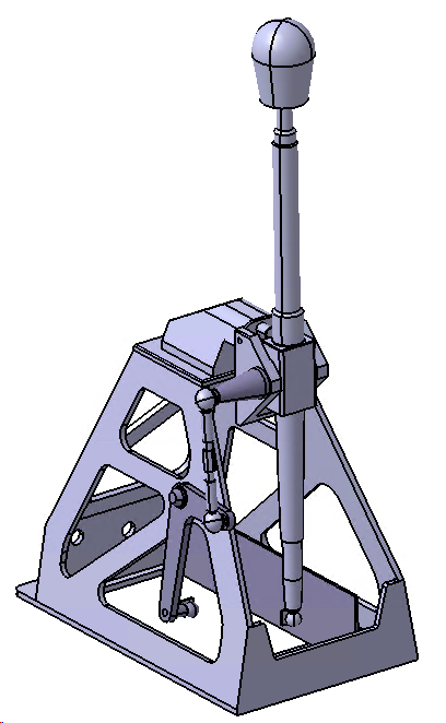
The Graphics Window should now look like the following picture.
The first thing we will do is create an Assembly and insert the parts. For other models, if you already have an Assembly of your parts, you can use that for the 3DCS model. We will start from scratch for the tutorial.
•Go to File ![]() New and in the New dialog select Assembly for the Type and Design for the Sub-type.
New and in the New dialog select Assembly for the Type and Design for the Sub-type.
•Change the Name to "Lesson3 Manual Gear Shifter Asm" and click [OK].
The parts we will use in the assembly are in millimeters. We need to change the assembly file to use the same units.
•Select File ![]() Prepare
Prepare ![]() Model Properties.
Model Properties.
•Under Materials, click change to the right of Units.
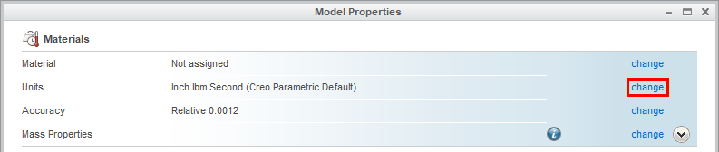
•In the Units Manager dialog, select millimeter Newton Second (mmNs) then click [Set...].
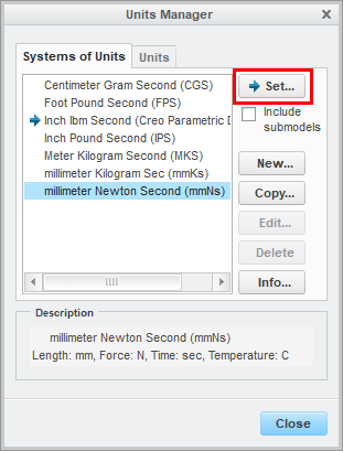
•In the Changing Model Units dialog, in the Model tab, select Convert dimensions then click [OK].
•Click [Close] in the Units Manager dialog.
•Click [Close] in the Model Properties dialog.
•In the Model tab, click the ![]() Assemble button.
Assemble button.
•Navigate to the User Lessons folder. The default location is in:
C:\Users\Public\Public Documents\DCS\3DCS_V5_8_2_0_0\Tutorials\Creo MVM tutorial
•Select Frame.prt. Click [Open].
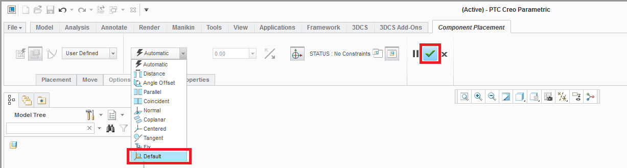
•From the Component Placement tab, select Default in the Relationship Type drop-down list (see image below). The status of the Frame will change to Fully Constrained.
•Select the Green Check Mark to exit the Component Placement workspace and place the Frame in its current, fully constrained position.
•Repeat this process to insert the remaining parts into the assembly.
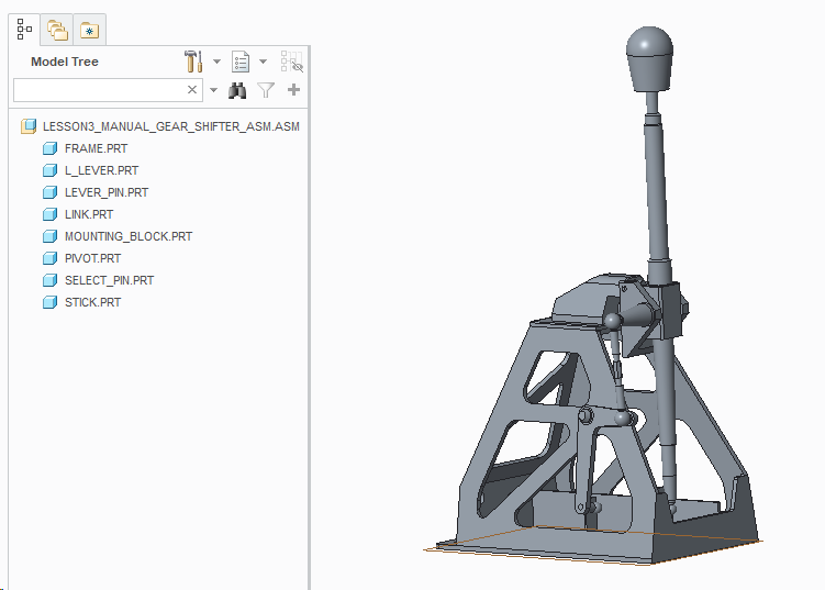
The Model Tree and Graphics Window should now look like the following picture.
The first thing we will do is create an Assembly and insert the Parts Frame, L Lever, Lever Pin, Link, Mounting Block, Pivot, Select Pin., Stick. For other models, if you already have an Assembly of your parts, you can use that for the 3DCS model. We will start from scratch for the tutorial.
•Select File ![]() New.
New.
•Under Templates, under Filters, set the Units to Millimeters if it is set to inches.
•Select Assembly and change the Name to "Lesson_3 Manual Gear Shifter Asm".
•Set the Folder to one that you have read/write access such as a folder on your desktop.
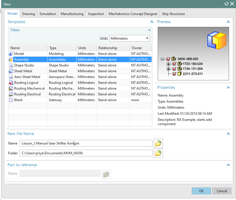
•Click [OK] in the New dialog.
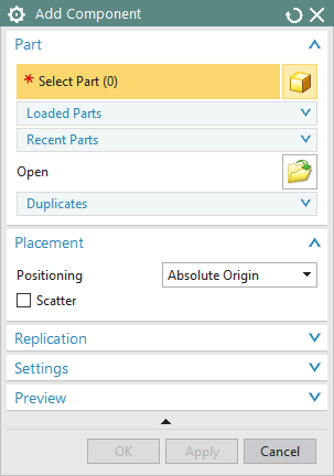
•In the Add Component dialog, click the ![]() Open button:
Open button:
•Navigate to the User Lessons folder. The default location is in:
C:\Users\Public\Public Documents\DCS\3DCS_V5_8_2_0_0\Tutorials\NX MVM tutorial
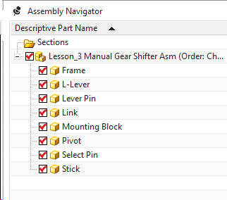
•In the Users Lessons folder, select the Frame, L Lever, Lever Pin, Link, Mounting Block, Pivot, Select Pin, and Stick. Click [OK].
•In the Placement section, set Positioning to Absolute Origin.
•Make sure the Scatter box is unchecked, If NX 12 this option will be available under Interaction Options.
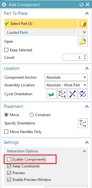
•Click [OK] in the Add Component dialog.
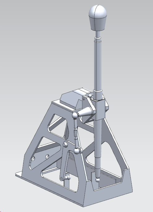
The Assembly Navigator tree and Graphics Window should now look like the following picture.
The first thing we will do is create a new Assembly and insert the parts. For other models, if you already have an Assembly of your parts, you can use that for the 3DCS model. We will start from scratch for the tutorial.
•Go to File ![]() New and in the New SOLIDWORKS Document dialog select Assembly.
New and in the New SOLIDWORKS Document dialog select Assembly.
•In the Begin Assembly dialog, select [Browse...].
•In the Open dialog, navigate to the User Lessons folder. The default location is in:
C:\Users\Public\Public Documents\DCS\3DCS_V5_8_2_0_0\Tutorials\SW MVM tutorial
•Select Frame.sldprt and click [Open].
•Select OK in the Begin Assembly tab to place the Frame at the origin.
• In the Assembly tab select![]() Insert Components and then [Browse...] to return to the Open dialog.
Insert Components and then [Browse...] to return to the Open dialog.
•Select Mounting Block.sldprt then once again select [Open] and ![]() OK.
OK.
•Repeat the previous steps to insert all the parts into the model at the origin.
•If you cannot see the imported parts, select the ![]() Zoom to Fit button to fit all parts in the window.
Zoom to Fit button to fit all parts in the window.
The display name for the assembly will be a default name (such as Assem1) until we save the model so next we must save the model with an appropriate name.
•Go to File ![]() Save As and change the name to "Lesson_3 Manual Gear Shifter Asm" and select [Save] to save the model and close the Save As dialog.
Save As and change the name to "Lesson_3 Manual Gear Shifter Asm" and select [Save] to save the model and close the Save As dialog.
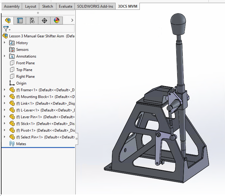
The Navigation Tree and Graphics Window should now look like the following image.
The parts we will use in the assembly are in millimeters. We need to ensure the assembly file is using the same units.
•Right click Lesson_3 Manual Gear Shifter Asm and select Document Properties.
•From the list on the left select Units and ensure that MMGS (millimeter, gram, second) is selected in the Unit system section.
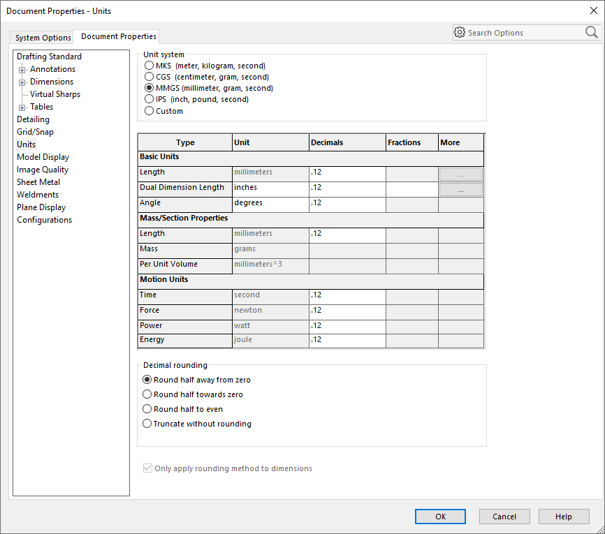
•Select [OK] to close the Document Properties dialog with the changes saved.
The first thing we will do is create a new model, which is an assembly of parts, and insert the Frame, L Lever, Lever Pin, Link, Mounting Block, Pivot, Select Pin., Stick. If your tree structure was already correct when you imported your CAD files, you can use that for the 3DCS model. We will start from scratch for the tutorial.
•Click the ![]() Application Button then select
Application Button then select ![]() New.
New.
•Double-click Root in the Navigation window to open the Edit Part dialog.
•Change the Name to "Lesson_3 Manual Gear Shifter Asm" then click [OK].
•Select the ![]() Application Button then Import
Application Button then Import ![]() HSF File.
HSF File.
•Navigate to the User Lessons folder. The default location is in:
C:\Users\Public\Public Documents\DCS\3DCS_V5_8_2_0_0\Tutorials\MC MVM tutorial
•Select the Frame.hsf, L Lever.hsf, Lever_Pin.hsf, Link.hsf, Mounting_Block.hsf, Pivot.hsf, Select_Pin.hsf, Stick.hsf and click [Open].
•If you cannot see the imported parts, select the Display tab then click ![]() Autoscale to fit all parts in the window.
Autoscale to fit all parts in the window.
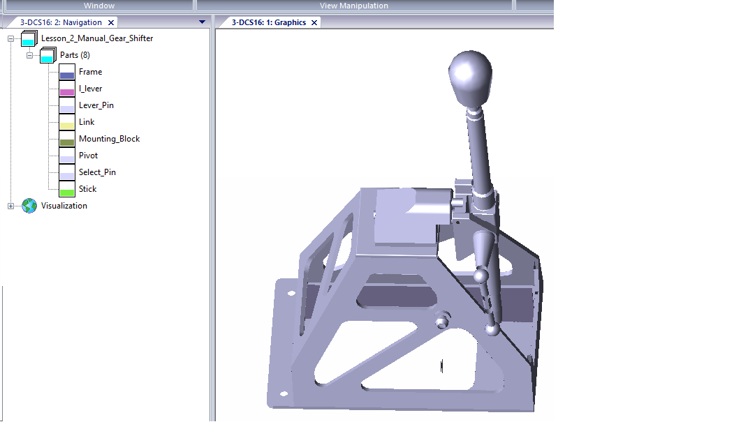
The Navigation Window and Graphics Window should now look like the following picture. The order of the parts may be different.