This document is the Technical Specification Document describing the technical details for the 3DCS enhancement – Kinematic Capabilities. This document intends to satisfy all of the requirements specified in the functional specification documentation (Functional Specification for 3DCS enhancement with Kinematic Capabilities - Nov. 11, 2003).This document intends to describe the 3DCS enhancement in handling Kinematics. Basically, there are two areas to be enhanced (a) Kinematic Joint (Constraint) User Interface and (b) Kinematic Joint Envelop Study (K-JES). In the following context, Kinematic Joint is denoted as K-joint.Related Documentation The following documents are referred to in this document. •Functional Specification for 3DCS Enhancement with Kinematic Capabilities
System Overview 3DCS is primarily used to simulate manufacturing processes and geometric tolerance, which are different from the constraints (K-joints) used in product design systems. 3DCS can simulate the constraints by using iterative moves. However, for a user with design experience, it is hard to understand the process simulation logic flow. Therefore, this issue becomes a problem of easy-of-use.
The other capability is related with kinematic envelope study. For example, in a suspension system, it is desired to simulate the several sequential positions (envelope) with an assembly sample. The envelope will tell whether a system is working within specifications for a range of motion. The other example is the roof-top-system on a convertible car. When the car is closing or opening the roof, the system should work with the specified efforts, which translates to the even gaps along the track for the roof-top-system.
A K-joint is designed as a 'process' (i.e. Move) in 3DCS. This enhancement will add the K-joints User Interfaces and K-JES functions to the existing capabilities. That means that a K-joint can be mixed with 3DCS regular moves.
|
|
Within this Section:Revolute Type (dcsRevolute) Slide Type (dcsSlide) Sphere Type (dcsSphere) Stop Plane Type (dcsStopPlane) Undo K-joint type (dcsKjUndo) Motion Translate Type (dcsKjMotionTranslate) Motion Rotate Type (dcsKjMotionRotate) Motion Points Type (dcsKjMotionPoints) Elastic Type (dcsKjElastic) Cylinder Align Type (dcsKjCylAlign) Group Floating (dcsKjGrpFloat) V-Plane-Cylinder Type (dcsKjVplaneCylAgainst)
|
|
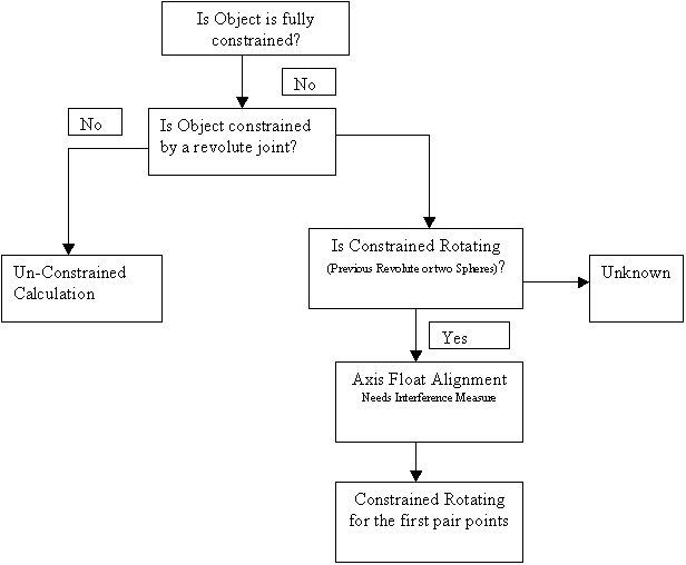
K-joint Process Model
Development Task
The development tasks are divided into two categories:
(a) K-joint functions
(b) K-JES functions.
(1) KJ Phase I
1. Revolute Type (dcsRevolute, or dcsKjRevolute): Axis coincident
DoF – one Remaining Rotation – one degree of freedom.
The joint type will be kept active once applied.
Symbol: ![]()
Point-Based:
{Object List: objPt1, objPt2} specifies an object axis.
{Target List: tgtPt1, tgtPt2} specifies a target axis.
Feature-Based (implemented later):
{Object List: objCyl}
{Target List: tgtCyl}
Floating is possible.
Action: the object component is constrained so that the object axis is co-linear with the target axis.
2. Slide Type (dcsSlide, or dcsKjSlide): Plane slide (Prismatic)
DoF – one Translation – one degree of freedom.
The joint type will be kept active once applied.
Point-Based:
{Object List: objPt1, objPt2} specifies an object axis.
{Target List: tgtPt1, tgtPt2} specifies a target axis.
Floating is possible.
Action: the object component is constrained so that the object axis is co-linear with the target axis while the associated direction at objPt1 is opposite to the associated direction at tgtPt1.
3. Sphere Type (dcsSphere, or dcsKjSphere): Spherical rotation (Ball Joint)
DoF – three rotations – three degree of freedom
The joint type will be kept active once applied.
Symbol: ![]()
Point-Based:
{Object List: objPt1} specifies the object sphere center.
{Target List: tgtPt1} specifies the target sphere center.
Feature-Based (implemented later):
{Object List: objSphere}
{Target List: tgtSphere}
Floating is possible.
Action: the object component is constrained so that the object center is located at the target center.
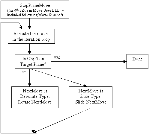
4. Stop Plane Type (dcsStopPlane, or dcsKjStopPlane): iterative
This type is used when a model requires the 'Stop' position on a plane, e.g. Suspension model requires the study on Ride Height (Z-height).
This move requires one parameter to tell how many following moves will be included in the iterative loop.
Point-Based:
{Object List: objPt1} specifies the object point.
{Target List: tgtPt1} specifies the target plane.
Control Parameter: the 4th constant in the move will indicate the number of moves to follow.
Floating is not possible.
Action: Iterate through the specified number of following moves to put the object point on the target plane (target pt, target direction)
Note: The first joint (has to be Revolute or Slide for now, 04/28/04/yz) following this Stop-Plane joint has to be the real driving joint.
5. Undo K-joint type (dcsKjUndo)
Action: undo all constraints specified by previous joints within its parent component.
This type is used when simulating a process, which requires undo previous constraints.
No parameters in this routine. Adding one object point to avoid validation checking error.
Floating is not possible.
6. Motion Translate Type (dcsKjMotionTranslate)
The type is really a move-deviating routine to deviate objects by specified values. The motion type is used to simulate 'driving range' in kinematic system for envelope study.
In Move User DLL GUI,
Constant #1 is the number of motion position – N.
Constant #2 is the 1st position.
Constant #3 is the 2nd position.
Point-Based:
{Object List: objPt1, objPt2, …} specifies the object point.
{Target List: tgtPt1, tgtPt2, …} specifies the target point.
Floating is not possible.
Action: All object Points in Object List will be deviated from its corresponding target point along the target point associated direction with the amount equal to the Constant value at that step.
That means:
objPt1_Pos = position_value_i * tgtPt1_Dir + tgtPt1_Pos.
objPt2_Pos = position_value_i * tgtPt2_Dir + tgtPt2_Pos.
Notes:
•In Nominal Build and not envelope run, this routine is skipped.
•In Build or Deviate, all the constants are looped through from Constant #2 to Constant #(N+1).
•In a regular Simulation, this Move should be turn off.
•In a K-JES Simulation, this Move will be used as Kinematic Driving Input.
7. Motion Rotate Type (dcsKjMotionRotate)
The type is really a move-deviating routine to deviate objects by specified values. The motion type is used to simulate 'driving range' in kinematic system for envelope study.
In Move User DLL GUI,
Constant #1 is the number of motion position – N.
Constant #2 is the 1st position.
Constant #3 is the 2nd position.
…
Point-Based:
{Object List: objPt1, objPt2, …} specifies the object point.
{Target List: tgtPt1, tgtPt2, …} specifies the target point.
Floating is not possible.
Action: All object Points in Object List will be rotated around its corresponding target point about the target point associated direction with the amount equal to the Constant value at that step.
That means:
objPt1_Pos = {initial objPt1_pos rotated at tgtPt1_Pos about axis = tgtPt1_Dir}
objPt2_Pos = {initial objPt2_pos rotated at tgtPt2_Pos about axis = tgtPt2_Dir}
Notes:
•In Nominal Build and not envelope run, this routine is skipped.
•In Build or Deviate, all the constants are looped through from Constant #2 to Constant #(N+1).
•In a regular Simulation, this Move should be turn off.
•In a K-JES Simulation, this Move will be used as Kinematic Driving Input.
8. Motion Points Type (dcsKjMotionPoints)
The type is really a move-deviating routine to deviate objects by specified target points. The motion type is used to simulate 'driving track' in kinematical system for envelope study.
In Move User DLL GUI,
Point-Based:
{Object List: objPt1, objPt2, …} specifies the object point.
{Target List: tgtPt1, tgtPt2, …} specifies the target point.
Floating is not possible.
Action: All object Points in Object List will be positioned in sequence at one target point. The target position and direction are used to set the object points' position and direction.
Notes:
• In Nominal Build and not envelope run, this routine is skipped.
• In Build or Deviate, all the target points are looped through starting from Target Point #1.
•In a regular Simulation, this Move should be turn off.
•In a K-JES Simulation, this Move will be used as Kinematical Driving Input.
•Added on 07/14/11/yz
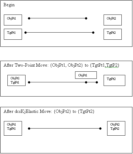
9. Elastic Type (dcsKjElastic): Move-Deviating Routine
This Type is used to simulate elastic (sprint) effect in a model.
This type is used when a feature (pt) is needed to match the target feature. For example, to stretch (bend) two object points (objPt1 and objPt2) to match the length between two target points (tgtPt1, tgtPt2). In this case, a Two-Point move is created co-linear with lines {objPt1, objPt2} and {tgtPt1, tgtPt2} and then a dcsKjBend Move is created with objPt2 in object list and tgtPt2 in target list. After these two moves, objPt1 = tgtPt1 and objPt2 = tgtPt2.
Floating is not possible.
10. Cylinder Align Type (dcsKjCylAlign): Axis Alignment
(Last modified on 05/02/04/yz)
Description: this routine is used to compensate the axis variation so that the in-alignment within each pair of axes can be limited within clearance.
Point-Based:
{Object List: objPt11, objPt12, objPt21, objPt22, objPt31, objPt32} specifies three object axes to be adjusted. Each point should be associated with a size entity. Maximum point number is equal to either (a) 4 (for Hole-Pin pairs) or (b) 6 (for Hole-Pin-Hole, e.g. Pin is the bolt).
{Target List: tgtPt11, tgtPt12, tgtPt21, tgtPt22} specifies two target axes to be aligned. Each point should be associated with a size entity. Assume axis2 = {tgtPt22 - tgtPt21} to axis1 = {tgtPt12 - tgtPt11}.
Action (future): the object axes are adjusted within clearance so that the in-alignment on the target axes can be minimized.
Action (current): rotate object part so that line {objPt11, tgtPt21} co-linear with line {objPt11, tgtPt11).
11. Group Floating (dcsKjGrpFloat): Group Floating with Checking
(Last modified on 05/25/04/yz)
Description: this routine is used to compensate the axis variation so that each pair revolute joint has the desired hole-clearance.
User Inputs:
In Values:
(1) First Value specifies the number of previous moves to be included in group floating
(2) Second Value specifies the maximum iterative number
In MeasList:
(1) Specify the list of measures to be checked within spec.
Action: Use initial seed (=1) to floating iteratively previous moves till all measures are satisfied – OK or till maximum iterative number is reached - FAIL.
Note: Ignore the warning for Empty Part List since no part is needed in this move.
12. V-Plane-Cylinder Type (dcsKjVplaneCylAgainst)
(Last modified on 11/29/04/yz)
This routine implements the 'against' constraint when two planes are tangent to one cylinder (circle).
DoF – One Remaining Freedom: One Translation.
Point-Based:
{Object List: objPt1, objPt2 with size} specifies a cylinder.
{Target List: tgtPt1, tgtPt2, with associated directions} specifies two target planes.
Action: the object component is constrained so that the object surface is mating with both planes (against).
Notes:
•No floating is expected.
•Using the average size between two ending circles in the calculation
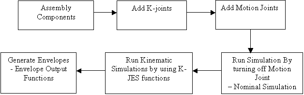
(b) Kinematic Simulation – Kinematic Envelope Study
User Routines - K-JES functions
There are four routines in the dcu_kinematic.dll:
1. Run Kinematic Function (dcsKjRunKinematic)
2. Envelope Function (dcsKjEnvelopeFunc)
3. Envelope Table Function (dcsKjEnvelopeTableFunc)
4. Run Kinematic HST Function (dcsKjRunKinematicHst)
1. K-JES - Run Kinematic Function (dcsKjRunKinematic)
Executing: Tools->RunDLL->"dcsKjRunKinematic"
Description: 3DCS will run a series of simulations and sensitivities and save an envelope file (CSV file) and multiple HST and HLM files.
Note1: Make sure files exist by checking DCS log file. Help->DCS Log File.
Note2: In case of failing to create the envelope file, execute Tools->RunDLL->"dcsKjEnvelopeFunc" to by-pass the simulation portion.
Use Motion Joint (dcsKjMotionTranslate and dcsKjMotionRotate) to create the motion. For each motion joint, a series of simulations and sensitivities are performed. The simulation (HST) files and sensitivity (HLM) files are saved in the report directory by the names kj_model_file_name_jointname_jointindex.
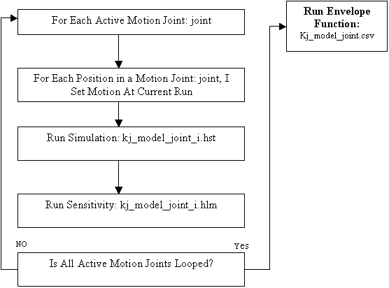
For example, a model file is dcs_kj_model.w3d, and the position number = 5. The following simulation files and sensitivity files are saved:
Dcs_kinematic_model_joint1_0.hst – simulation for Position 0
Dcs_kinematic_model_joint1_1.hst – simulation for Position 1
Dcs_kinematic_model_joint1_2.hst – simulation for Position 2
Dcs_kinematic_model_joint1_3.hst – simulation for Position 3
Dcs_kinematic_model_joint1_4.hst – simulation for Position 4
Dcs_kinematic_model_joint1_0.hlm – sensitivity for Position 0
Dcs_kinematic_model_joint1_1.hlm – sensitivity for Position 1
Dcs_kinematic_model_joint1_2.hlm – sensitivity for Position 2
Dcs_kinematic_model_joint1_3.hlm – sensitivity for Position 3
Dcs_kinematic_model_joint1_4.hlm – sensitivity for Position 4
2. K-JES – Envelope Function (dcsKjEnvelopeFunc)
Executing: Tools->RunDLL->"dcsKjEnvelopeFunc"
Action: Convert the series of HST files into a CSV file,
Containing Nominal -3Sigma +3Sigma Data format for Each Measurement.
3. K-JES – Envelope Table Function (dcsKjEnvelopeTableFunc)
Executing: Tools->RunDLL->"dcsKjEnvelopeTableFunc"
After simulations are successful, a kinematic (envelope) file is created as model_file_name_jointname_envelope.csv containing the envelope information divided into sections:
Section_1: Nominal
Section_2: Mean
Section_3: +3 sigma
Section_4: -3 sigma
Section_5: Max
Section_6: Min
The envelope file is listed by the measurements' name.
4. K-JES - Run Kinematic HST Function (dcsKjRunKinematicHst)
Executing: Tools->RunDLL->"dcsKjRunKinematicHst"
Description: This function is identical to 3.3.1 – Run Kinematic Function except that 3DCS will only run a series of simulations without HLM analysis.
(2) KJ Phase II – Customized GUI Solution
(This section will be defined later)
Appendix A Definitions
Kinematics
A kinematic analysis of a mechanical system specifies topology, degrees of freedom (DoFs), motions, and constraints, without specification of applied forces/torques or the mass properties of the bodies.
Joint
Represents one or more mechanical degrees of freedom between two bodies. Joints have no mass properties such as mass or an inertia tensor.
A joint primitive represents one translational or rotational degree of freedom or one spherical (three rotational degrees of freedom in angle-axis form). Prismatic and revolute primitives have motion axis vectors. A weld primitive has no degrees of freedom.
A primitive joint contains one joint primitive.
A composite joint contains more than one joint primitive.
Dynamics
A forward dynamic analysis of a mechanical system specifies:
•The topology of how bodies are connected
•The degrees of freedom (DoFs) and constraints among DoFs
•All the forces/torques applied to the bodies
•The mass properties (masses and inertia tensors) of the bodies
•The initial condition of all DoFs:
•Initial linear coordinates and velocities
•Initial angular coordinates and velocities
•The analysis then solves Newton's laws to find the system's motion for all later times.
Inverse dynamics is the same, except that the system's motion is specified and the forces/torques necessary to produce this motion are determined.
Dynamics is distinguished from kinematics by explicit specification of applied forces/torques and body mass properties.
Appendix B Stop-Plane Routine (Iteration Move) Type
Routine Name: dcsStopPlane.
GUI: Move User-DLL routine. Works with other Kinematic Joint Type. Internally use Iteration-Move routine.
Purpose: Simulate the kinematic model which requires the 'Stop' position on a plane, e.g. Suspension model requires the study on Ride Height (Z-height).
Input: one object pt and one target pt with an associated target direction.
Input: the 4th double in the move will indicate the number of moves to follow.
Output: Iterate through the specified number of moves to put the object pt on the target plane (target pt, target direction)
Notes:
•No floating is allowed in this move.
•No floating is allowed in the NextMove, which is the first move following this Stop-Plane Routine. In case floating is required for the NextMove, a dummy floating move can be used before the NextMove.
Appendix C:
Envelope file example:
"3DCS Analyst 6.0.1g Copyright(c)2003 By Dimensional Control Systems, Inc."
"File Name","D:\dcs_workdir\kj_suspension_Z_asm_motion_MoveMotionTranslate_envelope.csv","11/17/2003 ","16:34 "
"Data File","D:\dcs_workdir\kj_suspension_Z_asm_motion_MoveMotionTranslate_0.hst","11/17/2003 ","16:34 2636"
"Model File","E:\d_shared_files\b_dcs_models\dcs_models_dcs3d\dcs_kinematic_models\suspension\suspension_Z_asm_motion.w3d 11/17/2003 16:32 19370"
"Model Information","Part","7","Move","9","Tol","1","Meas","3","Pt","31"
"Simulation Run Time","0:0:1","Total Run","10","Initial Seed","1"
"MeasZ"," "," ","MeasArmAngle"," "," ","MeasPt"," "," "
" Nominal"," -3 Sigma"," +3 Sigma"," Nominal"," -3 Sigma"," +3 Sigma"," Nominal"," -3 Sigma"," +3 Sigma"
"60.000000","0.000000","0.000000","0.000000","-0.179942","0.179942","0.000000","-0.705817","0.705817"
"40.000000","0.000000","0.000000","0.000000","-0.114882","0.114882","0.000000","-0.723398","0.723398"
"20.000000","0.000000","0.000000","0.000000","-0.057550","0.057550","0.000000","-0.733750","0.733750"
"0.000000","0.000000","0.000000","0.000000","-0.037653","0.037653","0.000000","-0.736878","0.736878"
"-20.000000","0.000000","0.000000","0.000000","-0.084182","0.084182","0.000000","-0.732765","0.732765"
"-40.000000","0.000000","0.000000","0.000000","-0.148175","0.148175","0.000000","-0.721366","0.721366"
"-60.000000","0.000000","0.000000","0.000000","-0.214964","0.214964","0.000000","-0.702598","0.702598"
Appendix D
Envelope table file example:
"3DCS Analyst 6.0.1 Copyright(c)2003 By Dimensional Control Systems, Inc."
"File Name","H:\d_work_directory\3dCrank_MoveJoint1_envelope.csv","08/08/2003 ","16:39 "
"Data File","H:\d_work_directory\3dCrank_MoveJoint1_0.hst","08/08/2003 ","16:39 6551"
"Model File","H:\b_dcs_models\dcs_models_dcs3d\dcs_kinematic_models\3D_Crank\3dCrank.w3d 08/08/2003 15:46 17284"
"Model Information","Part","5","Move","5","Tol","2","Meas","2","Pt","13"
"Simulation Run Time","0:0:1","Total Run","100","Initial Seed","1"
"Section_1"," Nominal"
"MeasPt","MeasAng",
"0.000000","40.390980",
"0.000000","36.877686",
"0.000000","27.375381",
"0.000000","15.448191",
"0.000000","6.140744",
"0.000000","2.751255",
"Section_2"," Mean"
"MeasPt","MeasAng",
"-0.005510","40.390263",
"6.533330","40.390263",
"22.717549","40.390263",
"41.184737","40.390263",
"55.123111","40.390263",
"60.245068","40.390263",
"Section_3"," +3 Sigma"
"MeasPt","MeasAng",
"0.741067","0.508742",
"0.741067","0.508742",
"0.741067","0.508742",
"0.741067","0.508742",
"0.741067","0.508742",
"0.741067","0.508742",
"Section_4"," -3 Sigma"
"MeasPt","MeasAng",
"-0.741067","-0.508742",
"-0.741067","-0.508742",
"-0.741067","-0.508742",
"-0.741067","-0.508742",
"-0.741067","-0.508742",
"-0.741067","-0.508742",
"Section_5"," Max"
"MeasPt","MeasAng",
"0.540156","40.876746",
"7.078996","40.876746",
"23.263215","40.876746",
"41.730403","40.876746",
"55.668777","40.876746",
"60.790734","40.876746",
"Section_6"," Min"
"MeasPt","MeasAng",
"-0.610625","39.983381",
"5.928215","39.983381",
"22.112434","39.983381",
"40.579622","39.983381",
"54.517996","39.983381",
"59.639953","39.983381",
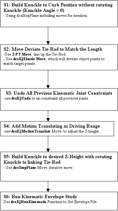
Appendix E
Suspension Envelope Study
Modeling the effect in adjusting Tie-Rod Length:
Appendix F Routine Mechanism
KJ - Revolute Type