The purpose of this routine is to locate an object to a target, in which one or more features simultaneously establish the primary locating plane. Consideration of the center-of-gravity will stabilize the object to the target primary plane.
Nest move operates only on the primary mating faces in the sense that it cannot float a pin/hole for secondary or tertiary. Therefore the Nest move requires a preceding move to position for the secondary and tertiary locators. For instance, using a preceding step-plane move is good because it locates in all 6 degrees of freedom. Then the following Nest move "over-writes" the primary location with a new position of the primary mating faces based on 3 high-point contact.
Background:The "Nest" move is very similar to the Autobend Move in its High Points mode, operating only on the primary mating surfaces, except Nest move also considers the center-of-gravity (or force direction) when mating faces. Of two mating faces that have multiple point pairs, it mates the faces based on the 3 "highest" point contacts between the faces, and searches for the 3 highest points based on the location & direction of a force/gravity. The nickname "keystone" comes from its first conception as a routine to assemble an intake manifold on a V-configured engine; it has the general shape of the keystone in a classical architectural arch but can be used in several other applications. •For one example, it can be used to position an Oil Pan onto three parts, across two mating T-joints. That is, the Oil Pan has to mate to the engine Block, and the Engine Front Cover, and the Engine Rear Cover. Nest move can be used to select the 3 high-points to mate across all the components. •Another example, Nest move can be used to position an angle bracket to a block. Here it considers two skewed faces as the primary mating faces.
Within this Section:Objective Inputs Assumptions and Limitations
|
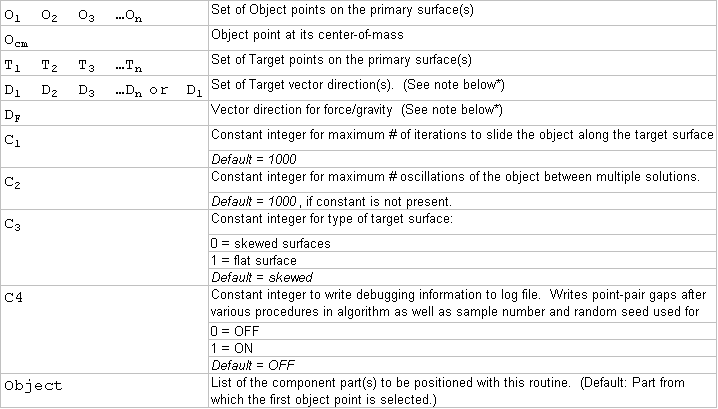
Objective:•Move an object to a target. •The object nests between target surfaces without bias to one primary feature or another. •All gap measurements from target to object will be -1e-06 or greater. The Gap is measured from the Target Point to the corresponding Object Point along the vector defined by the Target surface. The target surface is defined as varied surface patches, possibly on multiple features. Gap distances measured along target deviated vectors at each point-pair shall be greater than or equal to zero (-1e-06 or greater); i.e., "high-point" location. •There will be a minimum of three contact points (within 1e-06) which make-up the derived primary locating plane. •The object center-of-gravity is within the boundaries of the derived primary locating plane triangle when projected along the gravity vector. Inputs:•A minimum input of 3 point-pairs (nodes) for the object and target. No maximum number of point-pairs. •Corresponding points on the object and target – all primary locating surface(s). •A vector for each target point. •A center of gravity point on the object. •A force/gravity direction defined in the move dialog •Several control integers to define algorithm behavior.
|
|---|
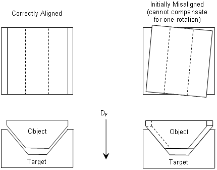
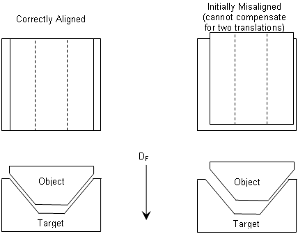
Assumptions:•Object part is roughly located with an initial move prior to calling this function. •Point-pairs are spread over the extents of the surface(s) of the object to be moved. •No bending or deformation of the part is performed. •If the object center-of-gravity point and the gravity vector do not intersect any candidate primary locating triangles, then …? •Object & Target point-pairs are nearly coincident when built. •For Object & Target meshes, nodes are equidistant; i.e., points are consistently spaced across the surface(s). |
|---|
Notes:•Requires a minimum of at least 4 ObjPts, at least 3 TgtPts, 2 Dir, and 1 object. Alternative argument lists: •If there are only 2 directions in the direction list, then the routine will use D1 for all target surface points, and the second direction for the force/gravity direction DF. This will apply only if all the point vector directions are same or if there is a previous move to do the primary location. •If there are more than 2 directions in the directions list, then the routine will associate each target point-pair to a separate direction D1 D2 D3 …Dn. The number of directions must be the number of target-point pairs plus one for DF. |