The document provides an overview of DCS ![]() Gear Modeling Utility (DCS GMU), a Dialog-based utility to facilitate the gear modeling. The objective for modeling a gear system is to produce the variation calculation for the following:
Gear Modeling Utility (DCS GMU), a Dialog-based utility to facilitate the gear modeling. The objective for modeling a gear system is to produce the variation calculation for the following:
Measurements
Angular Backlash
Pressure Angle
Axial Backlash
Mounting Angle
Mounting Distance
Flank Test
Procedure
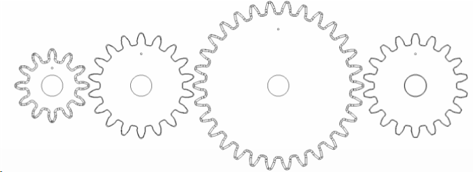
•The analyst builds the model with the gears and the appropriate gear mesh refinement
• Create the bore cylinder center points
• Create the clocking points on the gear faces.
• Select the tooth contact surface features
• The GMU generates the required moves, measurement, values, points in the model for the analyst to utilize in the usual way for runs, animations and deviations.
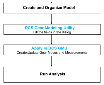
Create and Organize Model
Locate Parts for Tooth Selection
Translate / Rotate Gear Parts with spaces between the Gear Parts in its separated position making it easy for further modeling process.
Create Gear Points for Gear Module
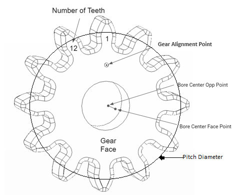
Each Gear requires at least three points: Alignment point, center1, and center2.
Use Feature Center Points to create the Bore Center Points. Create the alignment point on the Gear Face.
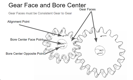
The gear face axis should be in the same direction for spur gears. The alignment point, also known as clocking point, tracks the gear rotation from nominal.
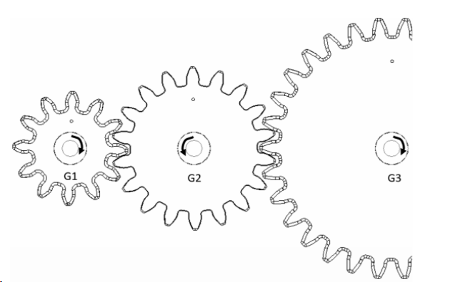
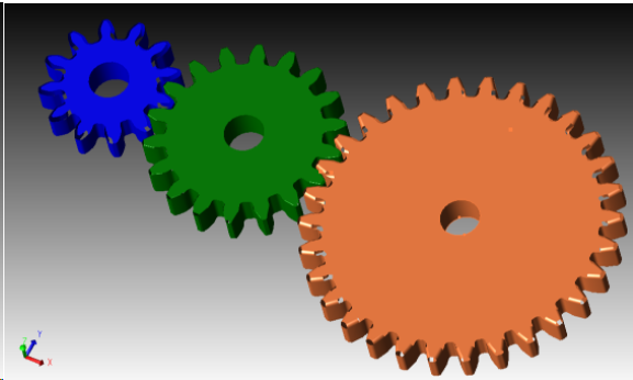
Gear G1 has a CW ClockWise, rotation using the axis emitted from the screen. G2 has a CCW Direction. The Gear Faces are on the same plane as the screen.
DCS Gear Modeling Utility
GMU collects the gear related information, e.g. gear numbers, driving gear, gear axial direction, gear points, gear mating surfaces and generate the Move and Measures required to calculate the Angular Backlash, Axial Backlash and Pressure Angle.
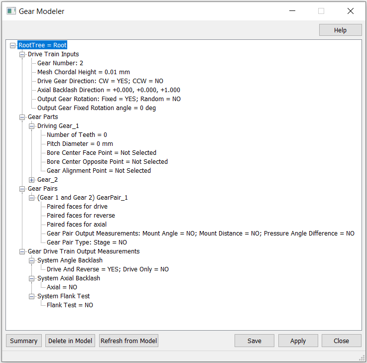
Drive Train Inputs
Gear Number
Right Click DriveTrain Inputs and Select Gear Number. This refers to the number of gears in the Drive Train. Select Gear Number and key in the number of gears.
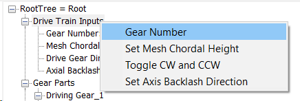
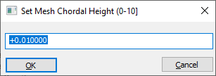
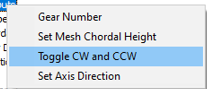
Set Mesh Chordal Height
Default 0.010 mm. Sets the maximum absolute distance (Sag) between the actual CAD design and the 3DCS Mesh.
Drive Gear Direction:
Drive Gear Direction: CW = Yes; CCW = No
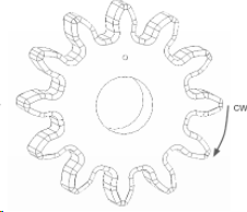
Gear Face is used to align the gears to determine the direction. Looking at Gear Face Direction, determine the Gear Drive rotation as CW, Clockwise - dial hand rotation direction of a clock, or CCW, counterclockwise in the opposite rotation direction. To change the Drive Gear Direction, select Toggle CW and CCW.
To Determine the Gear Direction:
1.Show the Gear Face on the Screen
2.Point your Right Hand Thumb Toward the Screen
3.CW is in the Direction of your curled fingers.
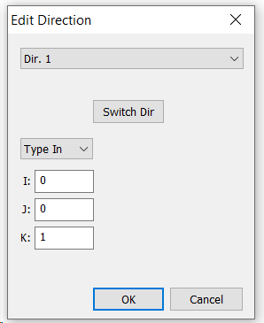
Axial Direction
The Axial Direction is the Direction for Axial Backlash. Z, (+0.000, +0.000, +1.0000) is the default Axial Direction shown above.
The Gear Faces must be consistently aligned gear to gear for the Drive Train. This face is used to select the input points on all the gears.
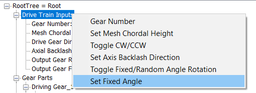
Output Gear Rotation
Set the Gear Rotation to be either Fixed or Random. If the Rotation is set to Fixed then the rotation angle should be specified.
Output Gear Fixed Rotation Angle
Right click on the Drive Train Input to set the rotation angle
Gear Parts
Enter each Gear in Drive Train order, starting with the Drive Gear.
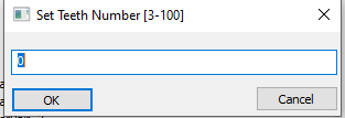
Right Click on Driving Gear_1, Select Teeth Number and Enter the Number of Teeth
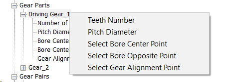
Similarly continue to pick the other fields by right clicking and selecting each item. Select the Bore and the alignments points that was initially created.
Repeat this for all the Gears.
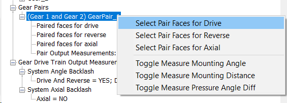
Gear Pairs
Gear Pairs connect pairs of gears together so the teeth mesh.
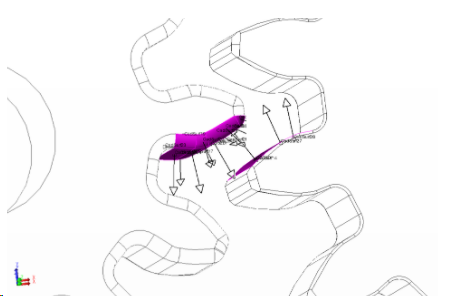
It is important to note which tooth surfaces on each gear are used to drive the adjacent gear drive tooth. Now select the G1G2 DriveFeature from the right click menu. Repeat the above procedure for the Reverse Contacts and Axial Contacts
Output Measurements
Define the Measurement outputs required both under Gear Pairs section and under Gear Drive train output measurements
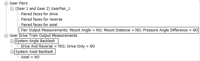
Angle Backlash:- Angle between the Drive Gear Clocking Position Point for Drive Contact and Reverse Contact for all the Pairs in the DriveTrain.
Axial Backlash:- The Axial Backlash between two gears is the distance between the nominal gear centers and with tooth contact. The measurement is along the selected Mounting Distance or axial direction.
Mounting Angle :- Angle between the Bore Axis of a Gear Pair
Mounting Distance :- Distance Between the Bore Center Face Points of a Gear Pair
Pressure Angle :- Angle Between the Drive Contact Normal and the Circular Tangent at the Contact Point for the first gear of the pair.
Flank Test:- This will trace the contact pattern between gears visually which shows mounting misallignment. ears are moved to a fixed position to trace the contact.
Apply in DCS Gear Modeling Utility (GMU)
Save
Saves the changes in the GUI into the GMU. If the model file is saved, the GMU will have the changes.
Apply
This will create the Moves and Measurements from the input entered in the GUI. Selecting apply, after making any changes in the GUI will Update the Moves and Measurements previously created.
Delete in Model
Deletes the GUI Moves. It is up to the user to Delete the Measures and added points in the Root and Gears.