In Creo, Components are assembled using the function called Placements. The Component Placement Interface consists of all constraints and Joints options for the user to place a component in its Assembly.
User can access to this Interface when a new component is brought into the assembly![]() or by rightclicking a component from the tree and can select the
or by rightclicking a component from the tree and can select the ![]() edit definition icon which opens this interface.
edit definition icon which opens this interface.
To Place a Component
• In an open assembly, click ![]() Assemble. The Open dialog box opens.
Assemble. The Open dialog box opens.
• Select the component to be placed and click Open. The Component Placement tab opens with the selected component in the graphics window. A component can also be selected from the browser and dragged into the graphics window.
•Select a connection type, User Defined is the default to configure a user-defined set. To place the components using Creo Constraints then the selection type need to set to User Defined.
•If you selected User-Defined, ![]() Automatic is selected by default. Select a reference on the component and a reference on the assembly, in any order, to define a placement constraint.
Automatic is selected by default. Select a reference on the component and a reference on the assembly, in any order, to define a placement constraint.
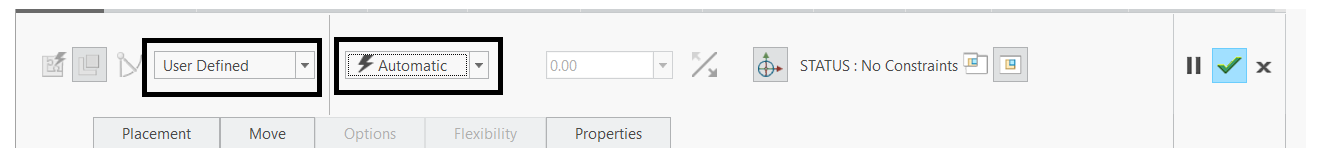
•When a pair of valid references is selected an appropriate constraint type is automatically selected.
•To Manually define a constraint, open the Placement tab. Choose a constraint type from the Constraint Type list.
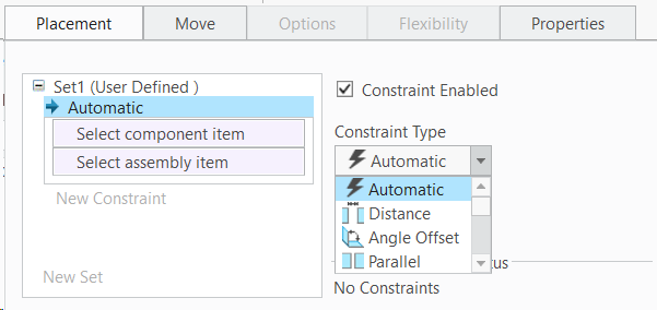
◦ ![]() Distance—Offsets the component reference from the assembly reference.
Distance—Offsets the component reference from the assembly reference.
◦ ![]() Angle Offset—Positions the component at an angle to the assembly reference.
Angle Offset—Positions the component at an angle to the assembly reference.
◦ ![]() Parallel—Orients the component reference parallel to the assembly reference.
Parallel—Orients the component reference parallel to the assembly reference.
◦ ![]() Coincident—Positions the components reference coincident with the assembly reference.
Coincident—Positions the components reference coincident with the assembly reference.
◦ ![]() Normal—Positions the component reference normal to the assembly reference.
Normal—Positions the component reference normal to the assembly reference.
◦ ![]() Coplanar—Positions the component reference coplanar to the assembly reference.
Coplanar—Positions the component reference coplanar to the assembly reference.
◦ ![]() Centered—Centers the component reference and the assembly reference.
Centered—Centers the component reference and the assembly reference.
◦ ![]() Tangent—Positions two references of different types so that they face each other. The point of contact is a tangent.
Tangent—Positions two references of different types so that they face each other. The point of contact is a tangent.
◦ ![]() Fix—Fixes the current location of a component that was moved or packaged.
Fix—Fixes the current location of a component that was moved or packaged.
◦ ![]() Default—Aligns the component coordinate system with the default assembly coordinate system.
Default—Aligns the component coordinate system with the default assembly coordinate system.
◦ ![]() Automatic—Shows available constraints in the list after you choose a reference.
Automatic—Shows available constraints in the list after you choose a reference.
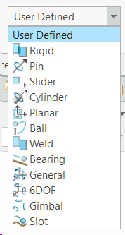
Joints
In the Placement Tab, User Defined section will allow us to create constraints, followed by that the other connection types replicate the Joints.
◦ ![]() Rigid—Allows no movement in the assembly.
Rigid—Allows no movement in the assembly.
◦ ![]() Pin—Contains a rotational movement axis and translation constraints.
Pin—Contains a rotational movement axis and translation constraints.
◦ ![]() Slider—Contains a translational movement axis and rotation constraints.
Slider—Contains a translational movement axis and rotation constraints.
◦ ![]() Cylinder—Contains a 360° rotational movement axis and translational movement.
Cylinder—Contains a 360° rotational movement axis and translational movement.
◦ ![]() Planar—Contains a planar constraint to allow rotation and translation along the reference planes.
Planar—Contains a planar constraint to allow rotation and translation along the reference planes.
◦ ![]() Ball—Contains a point alignment constraint for 360° movement.
Ball—Contains a point alignment constraint for 360° movement.
◦ ![]() Weld—Contains a coordinate system and an offset value to "weld" the component in a fixed position to the assembly. ◦
Weld—Contains a coordinate system and an offset value to "weld" the component in a fixed position to the assembly. ◦ ![]() Bearing—Contains a point alignment constraint to allow rotation along a straight trajectory.
Bearing—Contains a point alignment constraint to allow rotation along a straight trajectory.
◦ ![]() General—Creates a user-defined set of two constraints.
General—Creates a user-defined set of two constraints.
◦ ![]() 6DOF—Contains a coordinate system and an offset value, to allow movement in all directions.
6DOF—Contains a coordinate system and an offset value, to allow movement in all directions.
◦ ![]() Gimbal—Contains a coordinate system on the part and a coordinate system in the assembly to allow rotation in all directions about a pivot axis.
Gimbal—Contains a coordinate system on the part and a coordinate system in the assembly to allow rotation in all directions about a pivot axis.
◦ ![]() Slot—Contains a point alignment to allow rotation along a non-straight trajectory.
Slot—Contains a point alignment to allow rotation along a non-straight trajectory.
•Once the constraint type is selected go ahead and select the surface of the component and then the surface of the assembly component.
•The selected information get displayed under the user defined set
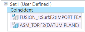
•Once a constraint in a user-defined set has been defined, a new constraint is automatically activated, until the component is fully constrained.
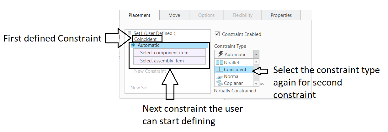
• The Placement Tab will also tell if a part is Fully Constrained or Partially constrained or no Constraints.
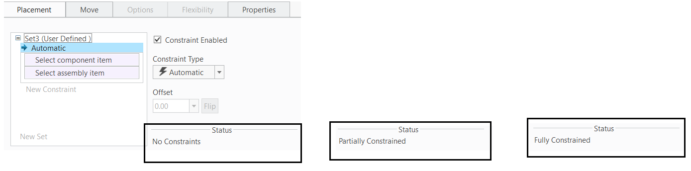
•A component cannot be placed in the assembly if the status is Connection definition is incomplete. You must complete the constraint definition first.
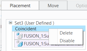
•Constraints in user-defined sets can be selected and edited. You can change the references or constraint type.
•To delete a constraint, right-click the constraint under the placement tab and select Delete from the shortcut menu.
• Click ![]() to place the component after defining the Constraints. The system places the component with the current constraints.
to place the component after defining the Constraints. The system places the component with the current constraints.
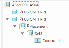
To Display Constraint Sets in the Model Tree
• Click ![]() > Tree Filters. The Model Tree Items dialog box opens.
> Tree Filters. The Model Tree Items dialog box opens.
• Click the Placement folder check box.
• Click OK. The Placement folder (indicated by ![]() ) appears as the first folder beneath the component in the Model Tree.
) appears as the first folder beneath the component in the Model Tree.
Extract Creo Placements into 3DCS
![]() Extract Joints and Constraints
Extract Joints and Constraints
Extract the Joints and constraints command will extract the defined Creo Placements and apply them as Mechanical Moves in 3DCS
The Table below shows the extracted 3DCS constraints for the Creo Constraints
Creo Constraints |
3DCS Constraints |
|||||
|
3DCS Extraction Information |
|||||
Creo Constraints Type |
Supports |
Creo's Orientation |
Extracted/ Contact |
Extracted/ Target Direction |
Extracted/ Constraint Type |
|
CONSTRAINTS |
||||||
Automatic |
|
|||||
|
||||||
Coincidence |
Axis/Axis |
|
N/A |
Default |
Coincidence |
|
Axis/Plane |
|
N/A |
Default |
Coincidence |
||
Plane/Plane |
Orientation1 |
N/A |
Align |
Coincidence |
||
Plane/Plane |
Orientation2 |
N/A |
Against |
Coincidence |
||
|
|
|||||
Distance |
Axis/Axis |
|
Default |
Default |
Offset |
|
Axis/Plane |
|
Default |
Default |
Offset |
||
Plane/Plane |
Orientation1 |
Default |
Align |
Offset |
||
Plane/Plane |
Orientation2 |
Default |
Against |
Offset |
||
|
|
|||||
Coplanar |
|
|
||||
|
|
|||||
Angle offset |
Axis/Axis |
|
Default |
Default |
Angle |
|
Axis/Plane |
|
Default |
Default |
Angle |
||
Plane/Plane |
Orientation1 |
Default |
Align |
Angle |
||
Plane/Plane |
Orientation2 |
Default |
Against |
Angle |
||
|
|
|||||
|
|
|||||
Parallel |
Axis/Axis |
|
Default |
Default |
Angle (0°) |
|
Axis/Plane |
|
Default |
Default |
Angle (0°) |
||
Plane/Plane |
Orientation1 |
Default |
Align |
Angle (0°) |
||
Plane/Plane |
Orientation2 |
Default |
Against |
Angle (0°) |
||
|
|
|||||
Normal |
Axis/Axis |
|
Default |
Default |
Angle (90°) |
|
Axis/Plane |
|
Default |
Default |
Angle (90°) |
||
Plane/Plane |
|
Default |
Default |
Angle (90°) |
||
|
|
|||||
Tangent |
Pin/Pin |
|
Default |
Default |
Contact |
|
Pin/Hole |
|
Default |
Default |
Contact |
||
Pin/Plane |
|
Default |
Default |
Contact |
||
Hole/Plane |
|
Default |
Default |
Contact |
||
Hole/Hole |
|
Default |
Default |
Contact |
||
|
|
|||||
Fix |
Parts |
|
N/A |
N/A |
Fixed |
|
|
|
|
||||
Default |
Parts |
N/A |
N/A |
Fixed |
JOINTS |
||||||
Centered |
Axis/Axis |
Default |
Default |
Coincidence |
||
|
|
|
||||
Pin |
|
N/A |
Default |
Revolute |
||
|
|
|
||||
Cylinder |
Axis/Axis |
N/A |
Default |
Cylindrical |
||
|
|
|
||||
Planar |
Plane/Plane |
Orientation 1 |
N/A |
Align |
Planar |
|
Plane/Plane |
Orientation 2 |
N/A |
Against |
Planar |
||
|
|
|
|
|||
Bearing |
Point/Line |
N/A |
Default |
Point On Line |
||
|
|
|
||||
Slot |
Point/Multiple Lines |
N/A |
Default |
Point On Line |
||
|
|
|
||||
Ball |
Point/Point |
N/A |
N/A |
Spherical Joint |
||
|
|
|
||||
Slider |
Axis/Axis, Plane/Plane |
N/A |
Default |
Prismatic |
||
|
|