3DCS Lights are used to add realistic illumination and shadows to parts and assemblies. There are three distinct styles of lights (Local, Distant, and Spot), each able to illuminate a model in unique ways. With the ability to increase intensity and vary the color 3DCS allows for more realistic part rendering.
The user interface will be consistent with the existing 3DCS Variation Analyst based user interface.
View Menu Lights Options (View/Set View/Light Settings)
•Lighting On - This option shows the graph window with or without a lighting effect. The lighting effect shows depth and shadows to give a better graphic understanding of the part.
•Light Scaling - The object color is a function of the light falling on that object from each light source. The light from each light source is additive, which can cause a problem if there is more than one light source in a scene.When setting the light scaling, the lights' number, colors, positions, and types (distant, local, or spot) need to be taken into account. Also note that you can purposely set the light scaling too low, which will cause color values greater than 1.0 to be clamped at 1.0. This clamping is not an error; if done excessively, however, it can cause scenes to appear washed out.
•Ambient Lighting - the contribution from indirect sources of light can be approximated through ambient lighting. If there are no light sources in a given scene, the "ambient" light color is ignored. If there is at least one light, the software will do a full lighting calculation and the "ambient" color will define a diffuse background lighting coming from all directions. You would usually use a combination of specific light sources plus a small amount of ambient light. Ambient light applies to all geometry.
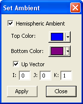
Ambient color can be set using Set Ambient dialog options:
![]() Hemispheric Ambient - If checked, HOOPS will apply ambient lighting to calculation for the color of a surface based on its normal vector and the value of the up vector which is (0,0,1) by default.
Hemispheric Ambient - If checked, HOOPS will apply ambient lighting to calculation for the color of a surface based on its normal vector and the value of the up vector which is (0,0,1) by default.
![]() Top Color - If Hemispheric Ambient is not checked, the color applies to the lighting calculations of all surfaces. If Hemispheric Ambient is checked, the color applies to the lightning calculation using the Up Vector information.
Top Color - If Hemispheric Ambient is not checked, the color applies to the lighting calculations of all surfaces. If Hemispheric Ambient is checked, the color applies to the lightning calculation using the Up Vector information.
![]() Bottom Color - If Hemispheric Ambient is checked, HOOPS uses this color as the light color in the opposite direction of the up vector when performing lighting calculations for surfaces.
Bottom Color - If Hemispheric Ambient is checked, HOOPS uses this color as the light color in the opposite direction of the up vector when performing lighting calculations for surfaces.
![]() Up Vector - The up direction of the Hemispheric Ambient lighting.
Up Vector - The up direction of the Hemispheric Ambient lighting.
Graph Window Lights Options
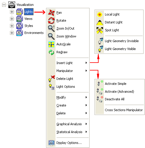
•Insert Light
![]()
![]() Local - Light is similar to a tiny light bulb and is infinitely small---it occupies only a point in space and radiates in all directions equally (omni-directional).
Local - Light is similar to a tiny light bulb and is infinitely small---it occupies only a point in space and radiates in all directions equally (omni-directional).
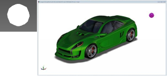
![]()
![]() Distant - Light is similar to the sun: it's so far away that all the light rays arriving from it are parallel.
Distant - Light is similar to the sun: it's so far away that all the light rays arriving from it are parallel.
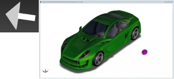
![]()
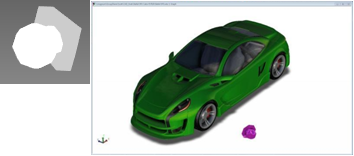
![]() Spot - Light is the most general type of "point" light source; it can behave not only like a sharp-edged spotlight, but also like a variable-focus flashlight, or a fuzzy-edged floodlight. These characteristics are determined from the light's position, target, illumination cone, edge sharpness, and concentration parameters.
Spot - Light is the most general type of "point" light source; it can behave not only like a sharp-edged spotlight, but also like a variable-focus flashlight, or a fuzzy-edged floodlight. These characteristics are determined from the light's position, target, illumination cone, edge sharpness, and concentration parameters.
![]()
![]() Light Geometry Invisible - Hides all active lights on screen.
Light Geometry Invisible - Hides all active lights on screen.
![]()
![]() Light Geometry Visible - Shows all active lights on screen.
Light Geometry Visible - Shows all active lights on screen.
Manipulator - To activate the Manipulator go to the Graph window and right-click on the desired light. This will activate the following options:
![]()
![]() Activate Simple - Turns on handles with translational control and rotational control.
Activate Simple - Turns on handles with translational control and rotational control.
![]()
![]() Activate Advanced - Turns on the same handles as "Activate Simple" with the addition of translational controls in the xy, yz, and xz planes.
Activate Advanced - Turns on the same handles as "Activate Simple" with the addition of translational controls in the xy, yz, and xz planes.
![]()
![]() Deactivate - Turns off selected handle.
Deactivate - Turns off selected handle.
![]()
![]() Deactivate All - Turns off all activated handles in the active model. This option is always available.
Deactivate All - Turns off all activated handles in the active model. This option is always available.
Note: When a Manipulator handle is active the size increases. Make sure that the correct handle is active before clicking to move the light.
![]()
![]() Cross Section Manipulator - shows or hides the section manipulator.
Cross Section Manipulator - shows or hides the section manipulator.
•![]() Delete Light - Removes selected Light.
Delete Light - Removes selected Light.
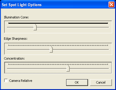
![]() Illumination (Outer) Cone - Specifies the size of a conic region of space inside which surfaces will be illuminated by this light. Outside the specified region surfaces receive no illumination.
Illumination (Outer) Cone - Specifies the size of a conic region of space inside which surfaces will be illuminated by this light. Outside the specified region surfaces receive no illumination.
![]() Edge Sharpness - Defines a second (interior) cone at which the light intensity starts to decrease linearly as you travel towards the illumination cone's edge (at which the intensity has decreased to zero) from the light-direction-vector.
Edge Sharpness - Defines a second (interior) cone at which the light intensity starts to decrease linearly as you travel towards the illumination cone's edge (at which the intensity has decreased to zero) from the light-direction-vector.
![]() Concentration - Changes the rate at which the light intensity decreases with increasing distance (in angular measure) from the light-direction-vector. Note the effect of concentration is in addition to the effect of edge sharpness. Edge sharpness applies only to the region between an inner cone and the illumination cone. Concentration effects the entire illuminated region.
Concentration - Changes the rate at which the light intensity decreases with increasing distance (in angular measure) from the light-direction-vector. Note the effect of concentration is in addition to the effect of edge sharpness. Edge sharpness applies only to the region between an inner cone and the illumination cone. Concentration effects the entire illuminated region.
![]() Camera Relative button - Normally the light's position and its target points are based in object space. "Camera Relative" tells the system the light should be attached to the camera's coordinate system --- thus the light is repositioned along with the camera when rotating the view.
Camera Relative button - Normally the light's position and its target points are based in object space. "Camera Relative" tells the system the light should be attached to the camera's coordinate system --- thus the light is repositioned along with the camera when rotating the view.
III. Navigation Window Lights Options - Use the right hand mouse button on Lights, LightSets, or individual Lights (Light1, Light2, etc) to open the sub-menus shown below.
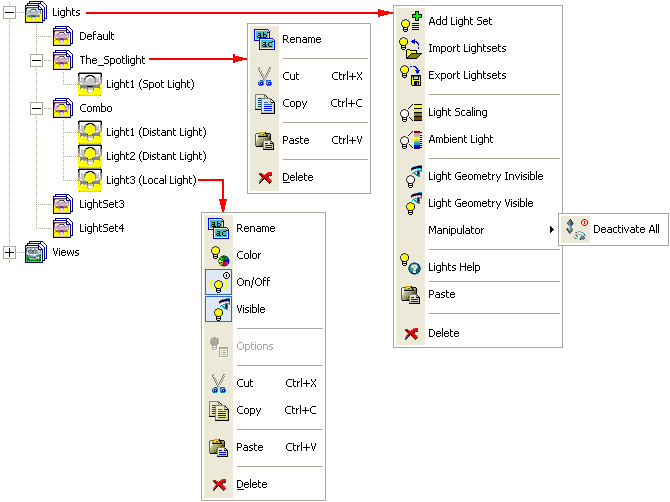
•![]() Lights (parent) contains all Light Sets created in the model.
Lights (parent) contains all Light Sets created in the model.
![]()
![]() Add Light Set - Creates a new light set.
Add Light Set - Creates a new light set.
![]()
![]() Import Lightsets - Loads light sets from an hsf file.
Import Lightsets - Loads light sets from an hsf file.
![]()
![]() Export Lightsets - Saves all light sets to an hsf file.
Export Lightsets - Saves all light sets to an hsf file.
![]()
![]() Light Scaling - Light scaling allows the users to adjust the intensity of the lights placed within a set. Once activated Light Scaling has an adjustable bar, and as the bar is adjusted the immediate effects can be seen in the graph window.
Light Scaling - Light scaling allows the users to adjust the intensity of the lights placed within a set. Once activated Light Scaling has an adjustable bar, and as the bar is adjusted the immediate effects can be seen in the graph window.
![]()
![]() Ambient Light - Ambient light controls the tint of a given light set, allowing you to change from the default "white light" to a custom color, using Set Ambient dialog options:
Ambient Light - Ambient light controls the tint of a given light set, allowing you to change from the default "white light" to a custom color, using Set Ambient dialog options:

![]()
![]() Light Geometry Invisible - Hides all active lights.
Light Geometry Invisible - Hides all active lights.
![]()
![]() Light Geometry Visible - Shows all active lights.
Light Geometry Visible - Shows all active lights.
![]()
![]() Manipulator/ Deactivate All - Deactivates manipulators for all lights.
Manipulator/ Deactivate All - Deactivates manipulators for all lights.
![]()
![]() Lights Help - Opens the Help Manual at the Lights page.
Lights Help - Opens the Help Manual at the Lights page.
![]()
![]() Paste - Pastes Light Set at the end of the Light Sets list.
Paste - Pastes Light Set at the end of the Light Sets list.
![]()
![]() Delete - Removes all created light sets.
Delete - Removes all created light sets.
•![]() Light Set is a set of one or more lights. The user can switch from one Light Set to another, by double-clicking on the new Light Set.
Light Set is a set of one or more lights. The user can switch from one Light Set to another, by double-clicking on the new Light Set.
![]()
![]() Rename - Changes the name of a Light Set.
Rename - Changes the name of a Light Set.
![]()
![]() Cut - Cuts Light Set.
Cut - Cuts Light Set.
![]()
![]() Copy - Copies Light Set.
Copy - Copies Light Set.
![]()
![]() Paste - Pastes Light Set at the end of the Light Sets list.
Paste - Pastes Light Set at the end of the Light Sets list.
![]()
![]() Delete - Removes a Light Set.
Delete - Removes a Light Set.
•![]() Light (individual)
Light (individual)
![]()
![]() Rename - Changes the name an individual Light.
Rename - Changes the name an individual Light.
![]()
![]() Color - Changes the emitted color of an individual Light.
Color - Changes the emitted color of an individual Light.
![]()
![]() On/Off - Toggles the selected Light on or off.
On/Off - Toggles the selected Light on or off.
![]()
![]() Visible - Makes the selected Light visible or invisible.
Visible - Makes the selected Light visible or invisible.
![]()
![]() Options - Available only for Spot Lights (see Light Options above).
Options - Available only for Spot Lights (see Light Options above).
![]()
![]() Copy - Copies the selected Light.
Copy - Copies the selected Light.
![]()
![]() Paste - Will paste the copied light in the selected Light Set.
Paste - Will paste the copied light in the selected Light Set.
![]()
![]() Delete - Removes an individual Light.
Delete - Removes an individual Light.
Note: The Lights and Light Sets can be rearranged using drag and drop options in the Navigation window.
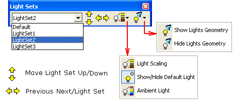
Notes:
•The Light Sets can be rearranged using Up and Down arrows options in the Light Sets toolbar.
•The Light Sets toolbar now expands to show full name for long names, when the toolbar is resized.
Process
1.Right click on the graph window in the general location that the light source is desired.
2.Click "Insert Light" and click on the desired light type.
3.Right click on the light geometry and click "Manipulator" then click "Activate Simple".
4.Use the activated handles to drag and rotate the light into the desired position.
5.Adjust the light sets "Light Scaling" until the desired results are reached.
6.Right click on the graph window and click "Insert Light" and choose "Light Geometry Invisible" to hide the created lights.
7.Right click on the graph window and click "Manipulator" then click "Deactivate All" to hide the light manipulators.
Note: All light sets are automatically saved with the model in a file named ModelName.dcs_gfx (the Save GFX (Visual) File option must be checked on in the DCS Preferences dialog).