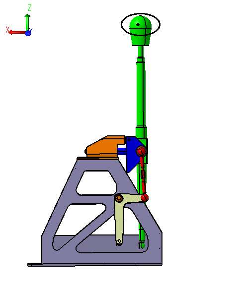
Basic Requirements needed for a Tolerance Simulation Model:
The required Inputs for MVM modeling are, Part Geometry, Assembly Method Moves, Part Tolerances and Measurements.
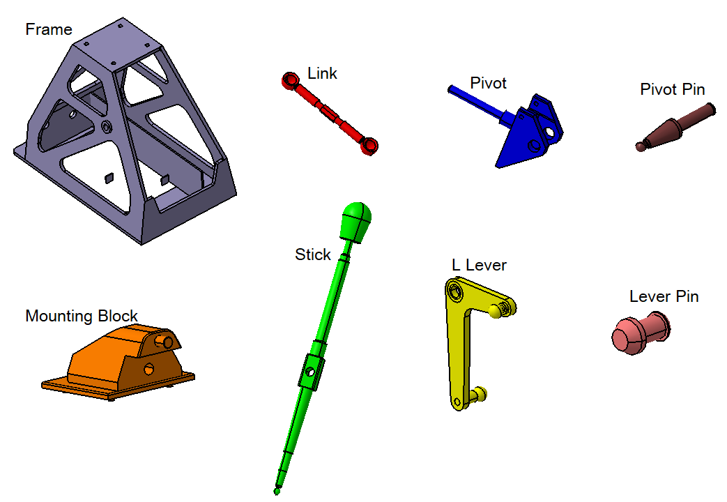
Part Geometry:
The first requirement of a model is the creation of part geometry. All part components that are analyzed have to be defined in the model.
Assembly Sequence:
This information is based on how the parts are sequentially put together in an assembly. This information is required for any model containing two or more parts. Within 3DCS, a Move defines how one part locates to another. Since each part has unique locators, appropriate moves have to be selected to assemble different parts together. Multiple moves can be defined to build an entire assembly.
This model utilizes sub-assembly modeling processes. It includes two sub assemblies, the Pivot Assy and the Lever Assy. These sub-assemblies need to be assembled first.
Pivot Assembly
 Coincidence Constraint between Pivot and Select Pin
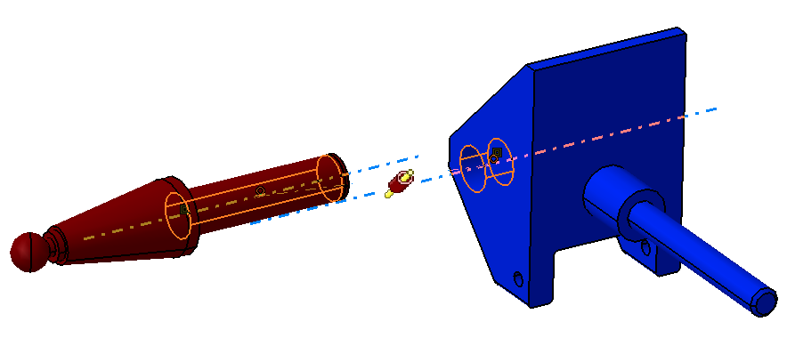
![]() Contact Constraint between Pivot and Select Pin
Contact Constraint between Pivot and Select Pin
![]() Fix Together Constraint between Pivot and Select Pin
Fix Together Constraint between Pivot and Select Pin
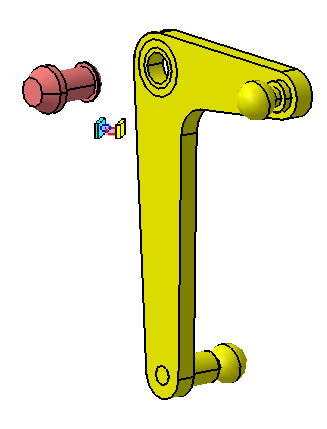
Lever Assembly
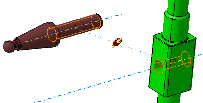
![]() Coincidence Constraint between L Lever and Lever Pin
Coincidence Constraint between L Lever and Lever Pin
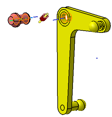
![]() Contact Constraint between L Lever and Lever Pin
Contact Constraint between L Lever and Lever Pin
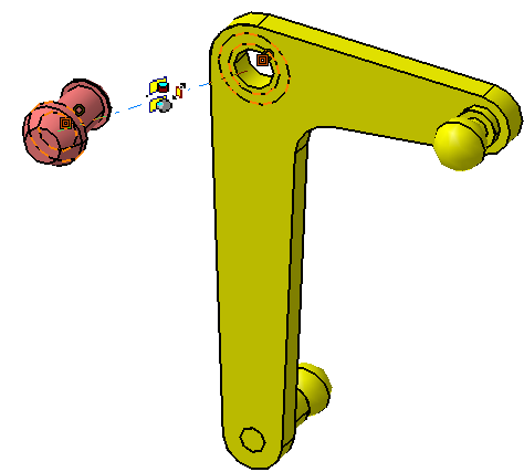
![]() Fix Together Constraint between L Lever and Lever Pin
Fix Together Constraint between L Lever and Lever Pin
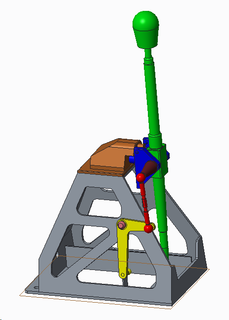
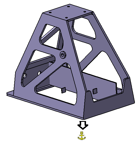
Main Assembly
![]() Fixed Constraint on Frame
Fixed Constraint on Frame
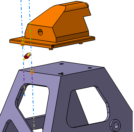
![]() Contact Constraint between Frame and Mounting Block
Contact Constraint between Frame and Mounting Block
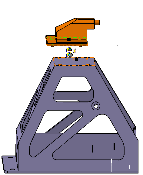
![]() Coincidence Constraint between Frame and Block
Coincidence Constraint between Frame and Block
![]() Coincidence Constraint between Frame and Block
Coincidence Constraint between Frame and Block
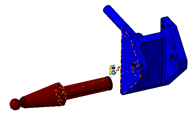
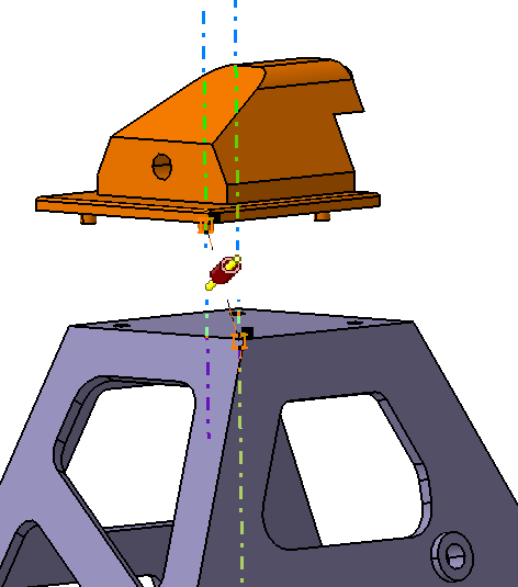
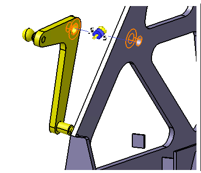
![]() Coincidence Constraint between Pivot and Mounting Block
Coincidence Constraint between Pivot and Mounting Block
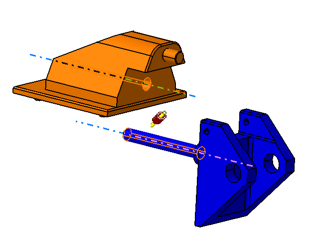
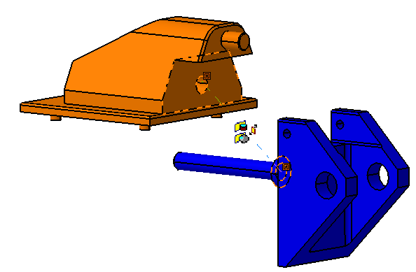
![]() Contact Constraint between Pivot and Mounting Block
Contact Constraint between Pivot and Mounting Block
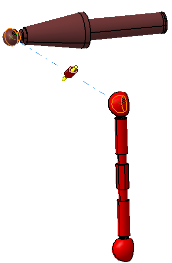
![]() Coincidence Constraint between Stick and Select Pin
Coincidence Constraint between Stick and Select Pin
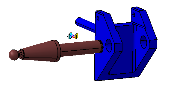
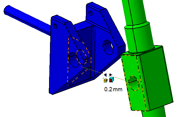
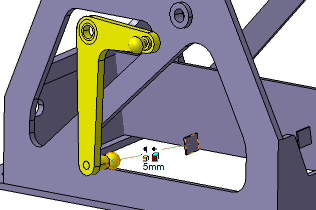
![]() Offset Constraint between Stick and Pivot
Offset Constraint between Stick and Pivot
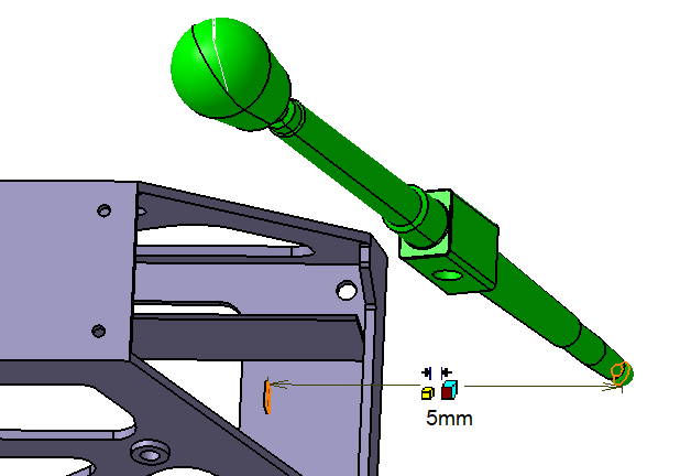
![]() Offset Constraint between Stick and Frame
Offset Constraint between Stick and Frame
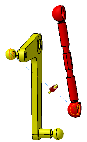
![]() Coincidence Constraint between Link and Select Pin
Coincidence Constraint between Link and Select Pin
![]() Coincidence Constraint between Link and L Lever
Coincidence Constraint between Link and L Lever
![]() Offset Constraint between L Lever and Frame
Offset Constraint between L Lever and Frame
![]() Revolute Joint between Lever and Frame
Revolute Joint between Lever and Frame
Tolerances:
3DCS MVM models are built and simulated to study the effects of tolerances in an assembly. Tolerances on the parts define the input variation. Proper definition and application of tolerances to the modeled areas of the parts are required.
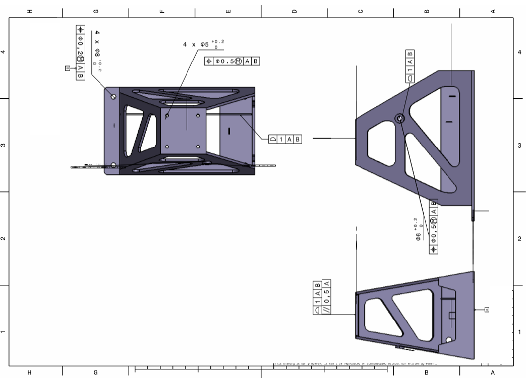
Frame
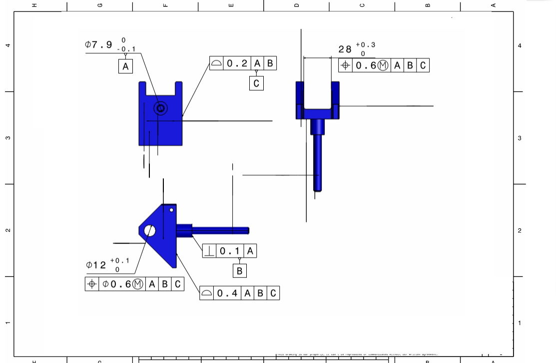
Pivot
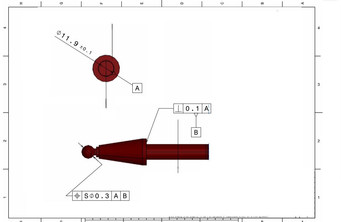
Select Pin
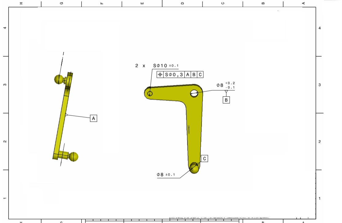
L Lever
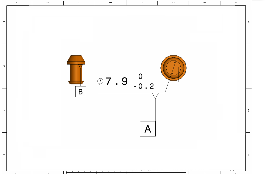
Lever Pin
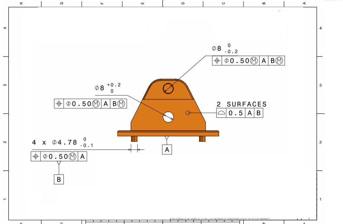
Mounting Block
Measurement Goal:
To understand the effects of Tolerances in a model, Measurements are defined in different areas of the model. Most measures will be made at the final assembly level (root level) of the model. These measures record the variation created in different areas of an assembly caused by the Parts, Tolerances and Assembly Method.
These are the measure results that are required from the model:
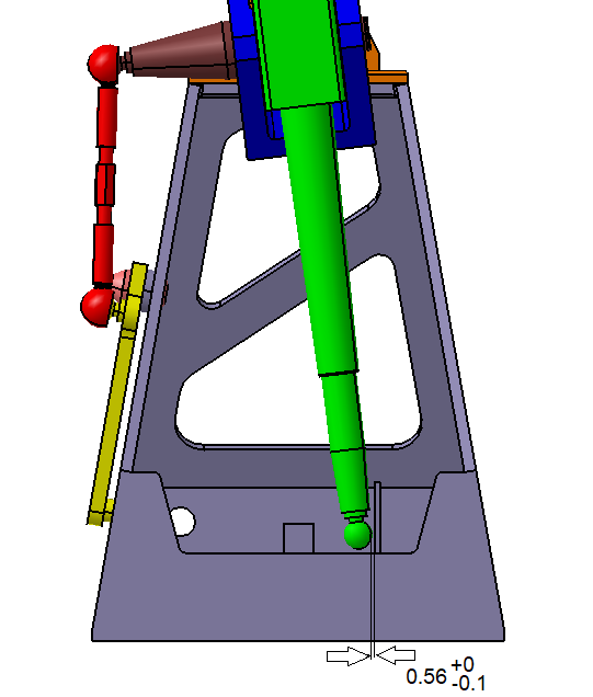
1. Measure the cylindrical surface of the Stick from Nominal in Y Direction to be within +/-1.
2. Measure the cylindrical surface of the Stick from Nominal in X Direction to be within +/-1.
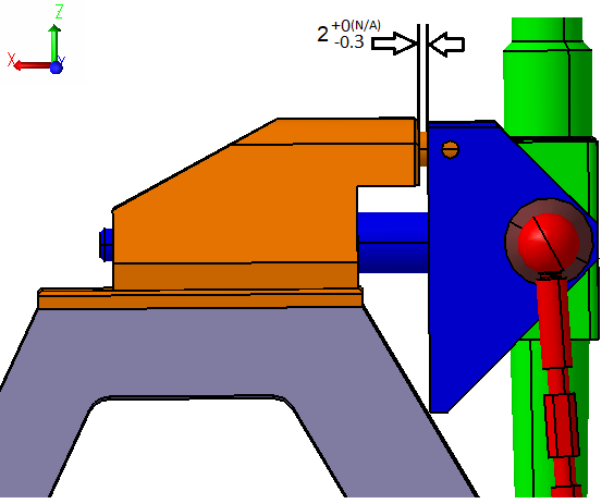
3. Determine the variation of the gap between Mounting Block and Pivot in the X direction.
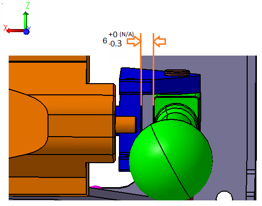
4. Determine the variation of the gap between the Pivot and Stick in the X direction.
5. Determine the variation gap between the lower sphere of the Stick and the surface of the Frame in the extreme position of the assembly.