Pin to Slot Clearance Measurement
Objective 1: To measure the pin to slot clearance (or lack of) in the major axis (slot length) direction.
Objective 2: To measure the pin to slot clearance (or lack of) in the minor axis (slot width) direction.
Objective 3: To find the percentage of builds with interference in either the minor axis
direction, major axis direction, or both directions.

Description of part measurements:
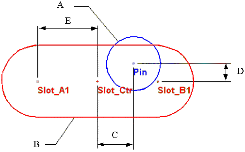
A: Radius measurement on the pin
Meas: Circle Diameter
Type: Circle Diameter
Scale: -0.5
B: Radius measurement on the slot
Meas: Circle Diameter
Type: Circle Diameter
Scale: 0.5
C1: Slot center to pin center distance in major axis direction
Meas: Point Distance
Type: Pt-Pt
Scale: 1.0
Dir: + major axis direction
C2: Slot center to pin center distance in opposite major axis direction
Meas: Point Distance
Type: Pt-Pt
Scale: 1.0
Dir: - major axis direction
D1: Slot center to pin center distance in minor axis direction
Meas: Point Distance
Type: Pt-Pt
Scale: 1.0
Dir: + minor axis direction
D2: Slot center to pin center distance in opposite minor axis direction
Meas: Point Distance
Type: Pt-Pt
Scale: 1.0
Dir: - minor axis direction
E: Half of slot flat length
Meas: Point Distance
Type: Pt-Pt
Scale: 1.0
Dir: Make sure output is always positive
Description of calculation measurements
F: Negative pin center to slot center in major axis distance
Meas: Combination
Type: Min Meas
Adding List:
C1, C2
G: Negative pin center to slot center in minor axis distance
Meas: Combination
Type: Min Meas
Adding List:
D1, D2
H: Objective 1
Meas: Combination
Type: Linear
Adding List:
A, B, E, F
Design Limits:
True SL (not relative), LSL = 0, USL = 100 (so you can't have "too much" clearance)
I: Objective 2
Meas: Combination
Type: Linear
Adding List:
A, B, G
Design Limits:
True SL (not relative), LSL = 0, USL = 100 (so you can't have "too much" clearance)
J: Objective 3
Meas: Combination
Type: In-Spec
Adding List:
H, I
Spec Limits:
Absolute SL (not relative), LSL = 1.9, USL = 2.1

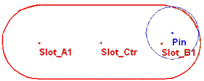
This measurement technique breaks down when the pin is "in the corners" of the slot (see above). In these cases, the condition passes both major and minor axis clearance criteria, but unless the slot is squared off, the pin will not fit. This is a small enough error percentage as to not be of concern unless the pin size is very small relative to the diameter of the slot.
Once the measurements are working correctly, the "As Output" box may be un-checked for measurements A through G.