The purpose of this method is to allow two parts with holes to be attached using a floating bolt. The results will not be exact because a simplification of the pin size tolerances is used.
|
|
Topics: |
Example Model:C:\Users\Public\Documents\DCS\3DCS_V5_8_2_0_0_win64\3DCS CAD & Example Models\Reference Models\Moves\Pattern move - Partial Pin |
Prerequisites:
| 1. | The pin diameter is always greater than the hole radius. |
| 2. | All hole-hole-pin pairs have approximately the same axis vector. |
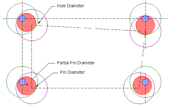
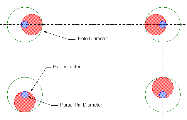
From the picture below, it can be seen that no matter where a pin floats in a hole, the blue part of the pin is always in the center of the hole. We will refer to this part as the partial pin. We can calculate its diameter with the following equation:
Partial Pin Diameter = 2 * (pin diameter - hole radius)
The equation simplifies to:
Partial Pin Diameter = 2 * pin diameter - hole diameter
If a second part is floated on the partial pins, the clearance through the pairs of holes is always greater than the pin diameter.
Method:
| 1. | Calculate the nominal partial pin size. |
Partial Pin Diameter = 2 * pin diameter - hole diameter
| 2. | Convert the smaller set of holes to pins. |
| 3. | With a 3 Point Move or other move, move the object to the target. This is needed to align the object surface(s) with the target surface(s). |
| 4. | Use a pattern move to float the object on the target.* |
| 5. | If any builds fail because of hole-pin interference, resolve with customer. |
Checks can be made to verify that the bolt can always fit in the opening between the actual object and target holes by modeling the original hole and grouping it with the partial pin in any tolerances. This can be time-consuming.
*The Pattern move is used when the fasteners are all first loose-fit and then tightened. If another process is modeled, the partial pin modeling can be used with the hole-pin floating in other move routines.
Size Tolerances:
The partial pin now represents both the pin and the hole it replaced.
| 1. | If the original hole had a position at MMC (bonus) tolerance, the partial pin should have the same size tolerance applied with the magnitude reversed (e.g. +0.1/-0.0 becomes +0.0/-0.1) so the bonus tolerance is applied correctly. |
| a. | Then, if the objective is to measure the ability of the parts to assemble, use the largest possible pin size in the partial pin equation. |
| b. | Otherwise, use the smallest possible pin size to maximize the variation. |
| 2. | If the original hole is not subject to bonus tolerance, calculate the size tolerance of the partial pin using the following equation: |
![]()
| Use the mean hole and pin diameters to calculate the offset if the hole or pin size tolerances are not equally distributed. |
The Pattern Move floats the purple Object holes on the blue partial pins.
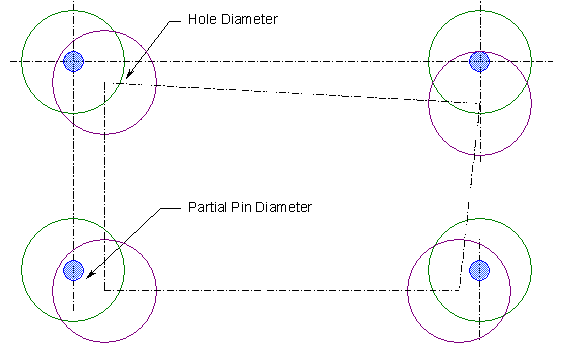
After the Pattern Move, the opening between the object and target holes is always large enough for the actual pin to pass through.