1. Tree Structure
1.1. The moves need to match the locators, not the assembly process nor the part tree.
1.2. For example, if two parts are loosely pinned together, then flanges on each part are attached to fixed parts, and finally the loose pin is tightened, then the moves for the flanges should be first.
1.3. For example, if two halves of a hinge are pinned together, then each half is welded to a part, then each half of the hinge must be treated as a separate part in the moves.
1.4. This means the CAD data part tree probably isn’t ideal. Rearranging the tree can save lots of time and trouble when modeling.
1.5. The simplest tree to work with is “flat.” The model contains a single assembly level and a set of child parts. This tree structure is strongly recommended for new 3DCS Mech user.
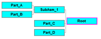
1.6. The most robust tree to work with has perfectly rigid sub-assemblies. In the example below, Mech or classic moves are used to constrain all six degrees of freedom (DoFs) between Part A and Part B. These moves can be in SubAsm 1 or the first moves in the Root (if they are in the Root, however, the modeler must take care that the correct move parts are selected.) Then, Mech moves can be used to constrain SubAsm 1, Part C, and Part D.

1.7. If Part A and Part B are not perfectly rigid, e.g. they are two halves of a hinge, then the tree is non-ideal. Without rearranging the tree, SubAsm 1 cannot be selected as the object or target move part in any moves.
1.7.1. The moves would be easier to create if Part A were moved into a sub-asm with the parts it is welded to and if Part B were moved into a sub-asm with the parts it is welded to.