Before Generating a Report it is important to save views for the created MTMs.
A Screenshot can be taken and saved along with the MTM in the Model, which will be used as report images for those MTMs when a Report is generated.
Save View
•Click [Save View] in any MTM dialog as well as in the MTM Tree right click menu to save a view for that MTM.

•Move the Assembly in the graphics to a desired view for the selected MTM and hit Save View.
•This will save the Screenshot to the MTM
•If a MTM have view saved it will be shown in the tree with a unique tree icon.

Show View
•Show View button is available under each MTM dialog and also in the MTM Tree right click menu next to Save MTM.

•This will show the view taken by the user in the graphic window.
Delete View
•Any saved view can be deleted using Delete view from the tree right click menu
•This will remove the tree icon for saved view.
Next, create the pages for the the report using the 3DCS Report toolbar is shown below.
![]()
•Select ![]() Report Cover Page (usually under
Report Cover Page (usually under ![]() Report Generation).
Report Generation).
This will open dcstemp.htm in a word processor like Microsoft Word. A default template is shown the first time Report Cover Page is opened for a model. Images and text can be saved in the Report Cover Page which will be shown on the first page of the report.
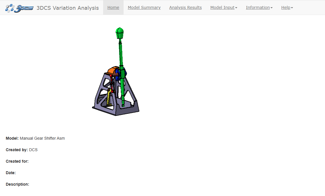
•Enter "Model: Manual Gear Shifter Asm" and "Created by: your name" into the Report Cover Page.
•In the Editing File in External Editor dialog, select [Save to File] to save the Report Cover Page
•Select [OK] in the new 3DCS dialog to automatically close the dcstemp.htm file.
•Select ![]() Model Summary.
Model Summary.
Like the Report Cover Page, this will open dcstemp.htm in a word processor like Microsoft Word. A default template is shown the first time Model Summary is opened for a model. Images and text can be saved in the Model Summary which will be shown in the Model Summary section of the report.
•Enter "Summary of the Gear Shifter Model." into the Model Summary.
•Paste any image into the Model Summary.
•In the Editing File in External Editor dialog, select [Save to File] to save the Model Summary.
•Select [OK] in the new 3DCS dialog to automatically close the dcstemp.htm file.
•Select ![]() Part Note then select the Bracket.
Part Note then select the Bracket.
Part Note is similar to the Model Summary but is saved for an individual part or subassembly instead of the top level. They appear in the Part Notes section of the report.
•In the Editing File in External Editor dialog, select [Save to File] to save the Part Note.
•Select [OK] in the new 3DCS dialog to automatically close the dcstemp.htm file.
•Select ![]() Nominal Build then
Nominal Build then ![]() Run Analysis.
Run Analysis.
•Minimize the Analysis Summary window. The Analysis Summary window must remain open to include the simulation and sensitivity in the report.
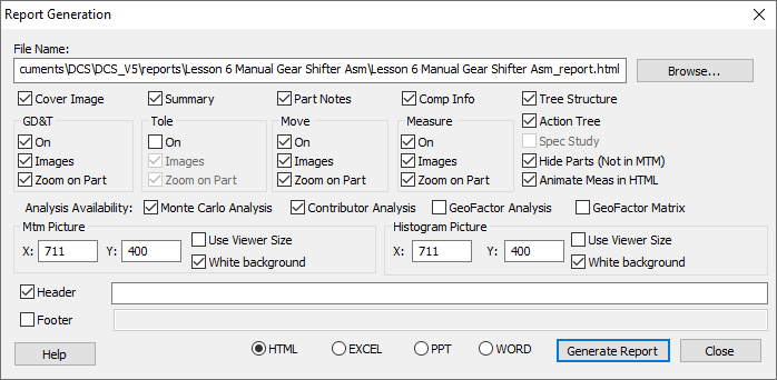
•Click ![]() Report Generation to open the Report Generation dialog. This dialog lets the user specify which parts of the model will be included in the report.
Report Generation to open the Report Generation dialog. This dialog lets the user specify which parts of the model will be included in the report.

•Check all boxes to include everything in the report except Use Viewer Size, GeoFactor Analysis and GeoFactor Matrix (leave these unchecked). Spec Study should be unavailable.
•Enter a Header and Footer.
•Set the format to HTML.
•Select [Generate Report]. If prompted by a warning about a previous report being overwritten, select [Yes] to continue.

Because we chose the HTML format, the report will open in your web browser. The Cover Image uses the orientation of the model when [Generate Report] was clicked. Images saved in the Report Cover Page will appear here. Use the tabs at the top to navigate to the different sections of the report.
•Click the Model Summary tab to see the text and image you entered.
•Click the Analysis Results tab to see a summary of the results for all of the measures in the model.
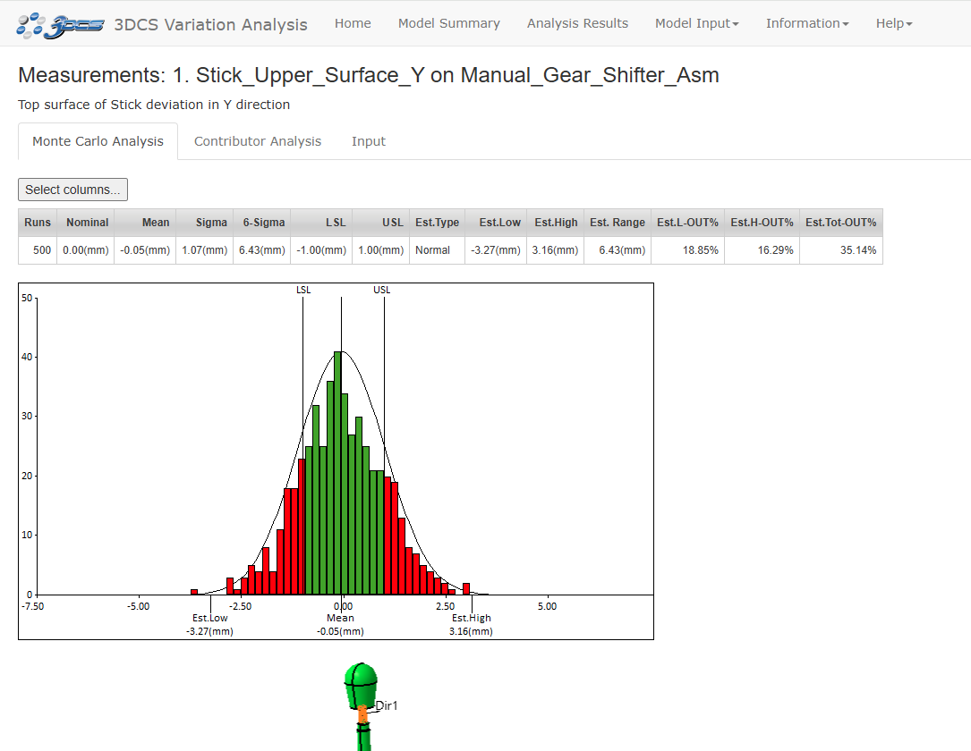
•Click Stick Upper Surface Y under the Name column to go to the detail page for that measure.

An image is created for every move, tolerance, measure, and GD&T in the model. The orientation of the parts when the report was generated is used by default but custom views can be saved by the user.
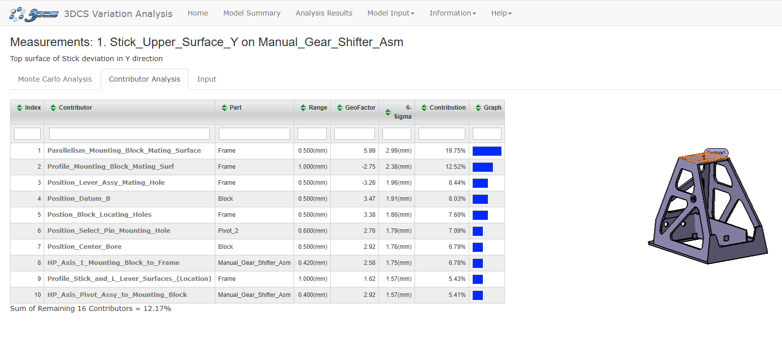
•Click the Contributor Analysis tab under the measure's name and description to see the contributors for that measure.

•Explore the rest of the report on your own.
•Return to 3DCS and generate reports in the other formats.