Point Distance Measurement
It is good practice to frequently save your work. We will do so before creating the measures.
•Go to File ![]() Save Management.
Save Management.
•Select the Lesson_3 Manual Gear Shifter Asm.CATProduct and select [Save As...].
•Navigate to a New folder and rename to "Lesson4" that will be easily accessible later.
•Click [Propagate Directory] to save a copy of the CATPart files to the new folder.
•In the Save As dialog, rename the Product to "Lesson_4 Manual Gear shifter AsmCATProduct" and click [Save].
•In the Save Management dialog select [OK] to save the CATIA Product under its new name. The model is not saved until you click OK.
•Open the 3DCS MVM workbench and click ![]() Update Model.
Update Model.
•Go to [File] ![]() [Save As].
[Save As].
•In the Save a Copy dialog, enter "Lesson_4 Manual Gear shifter Asm" for the File Name, make sure the Type is set to Assembly (*.asm), then click [OK].
•In the Assembly Save a Copy dialog, click [Save Copy and Open] to save the assembly under its new name, and open the newly saved assembly.
•Close the 3DCS Model Navigator and Creo window for Lesson_3 Manual Gear shifter Asm.
•Click ![]() Update Model in the new window for Lesson_4 Manual Gear shifter Asm.
Update Model in the new window for Lesson_4 Manual Gear shifter Asm.
•Go to [File] ![]() [Save As].
[Save As].
•In the Save As dialog, enter "Lesson_4 Manual Gear shifter Asm." as the new File name and make sure the type is set to Part Files (*.prt).
•Click [OK] in the Save As dialog.
•Click ![]() Update Model.
Update Model.
•Go to [File] → [Save As].
•In the Save as dialog, enter "Lesson_4 Manual Gear shifter Asm." for the File Name, and make sure the Type is set to Assembly (*.asm).
•In the Assembly Save as dialog, click [Save Copy and Open] in the bottom left of the dialog to save the assembly under its new name, and open the newly saved assembly.
•Click Update Model in the new window for Lesson_4 Manual Gear shifter Asm.
•Click the ![]() Application Button then select
Application Button then select ![]() Save As.
Save As.
•Change the File Name to "Lesson_4 Manual Gear Shifter Asm"and make sure the Type is set to WTX DATA(*.wtx)
•Click [Save] in the Save As dialog.
Measure 1: Shifter_Knob_Y_dir
•Click the ![]() Measures button from the Model Creation toolbar and select the top assembly from the tree, this will open the Measures dialog for this part.
Measures button from the Model Creation toolbar and select the top assembly from the tree, this will open the Measures dialog for this part.
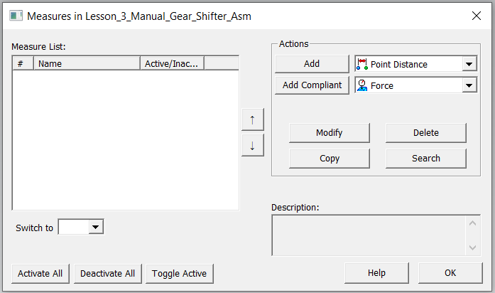
•Select ![]() Point-Distance from the pull down list and click the [Add].
Point-Distance from the pull down list and click the [Add].
•This will open the Point Distance Measure dialog.
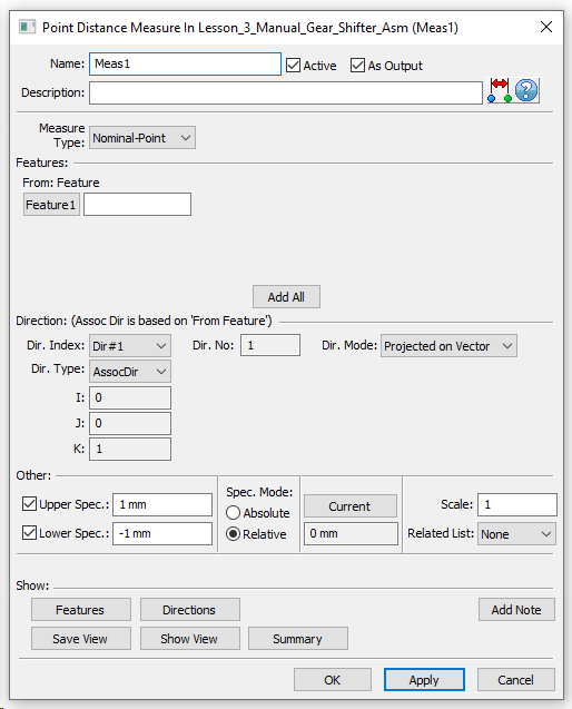
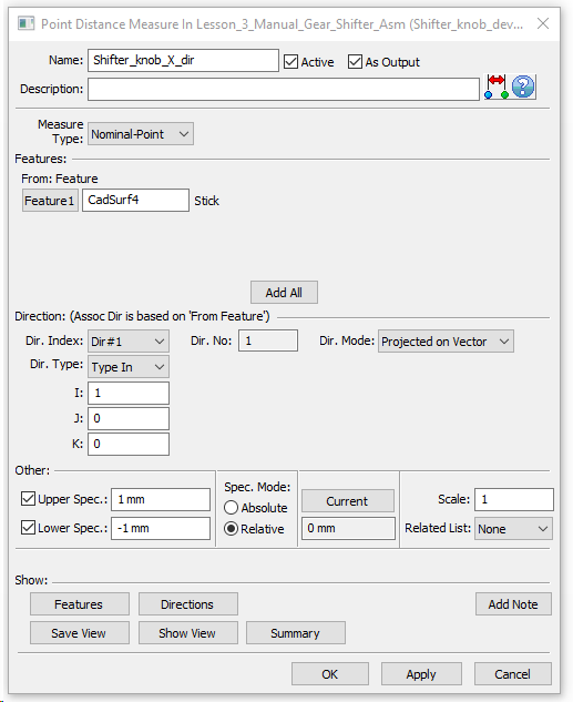
•Name this measure “Stick Upper Surface Y ". Give it the description "Top surface of Stick deviation in Y direction” (description is not mandatory).
•Select [Nominal-Point] for Measure Type.
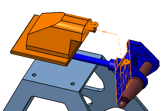
•Click [Add All] and select the surface highlighted on the Stick shown below.
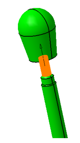
•Change the Dir. Type to "Type in" and set the vector direction to i=0, j=1, k=0 to only measure deviations in the Y direction.
•Set the Upper Spec to 1mm and Lower Spec to -1mm. Keep the Spec Mode set to Relative. Ask your trainer for more information on the topic of Spec Modes.
•The completed measure dialog will look similar to the image below.
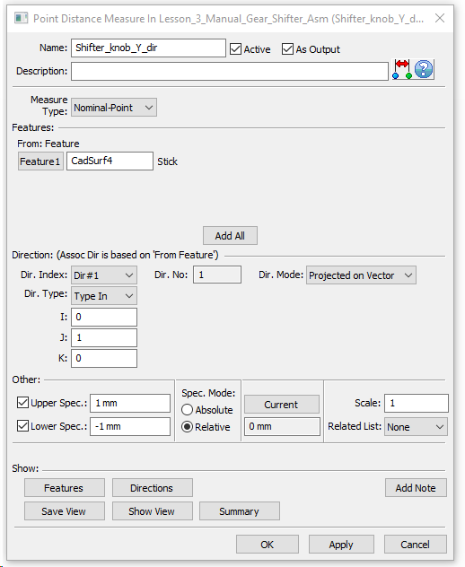
•Click [OK] to create the measure.
•Repeat the same process to create measurements for the second measure, “Stick Upper Surface X”. This measure will use the same feature but measure along the X direction.
Measure 3: Mounting_Block_and_Pivot Gap
Create a Point Distance Measurement between Mounting Block vertical surface and Pivot vertical surface.
•Reopen the Measures dialog for the top assembly part.
•Select ![]() Point-Distance from the pull down list and click [Add].
Point-Distance from the pull down list and click [Add].
•This will open a new Point Distance Measure dialog.
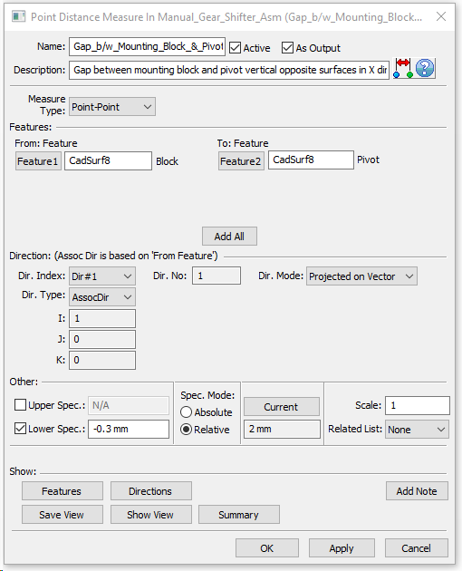
•Name this measure "Mounting Block and Pivot Gap". Give it the description: "Gap between Mounting Block and Pivot opposite vertical surfaces in X direction” (description is not mandatory).
•Select [Point-Point] for Measure Type.
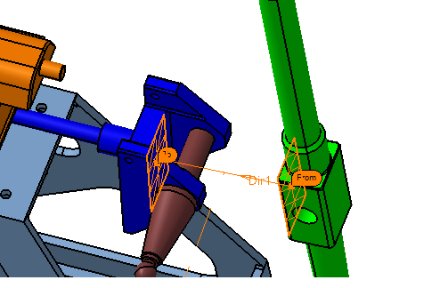
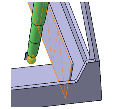
•Click [Add All] and select the surfaces on the Mounting Block and Pivot, respectively, shown in the image below.
•By default the Dir. Type will be set to Assoc Dir. This will use the direction from the first feature used in the measure as the measure direction
•To set the Spec. Limits, uncheck the Upper Spec box and set the Lower Spec to be -0.3mm and the Spec Mode to Relative. The upper spec limit is not required as the gap can’t grow too large.
•The completed measure dialog looks like the image below.
•Click [OK] to create the measure.
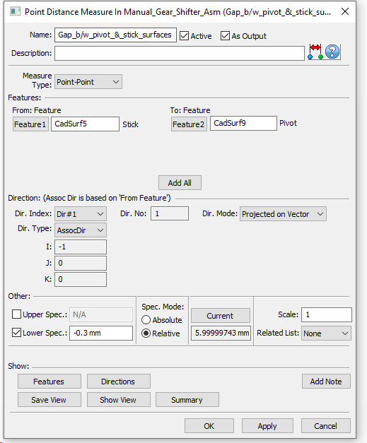
•Repeat the previous steps to create a Point Distance Measure with the name “Pivot and Stick Gap”. Pick the two features shown in the following picture. Be sure to select the surface on Pivot first, this will ensure the direction in the measure is set to the X direction.
•Give this measure a description of "Gap between Pivot and Stick opposite vertical surfaces in X direction".
•The completed measure dialog should look like the image below.
Feature Distance Measurement
Measure 5: Stick and Frame Plate Min Gap
Create a Feature Distance Measure between Stick bottom ball outer surface and Frame reinforcement surface.
•Reopen the Measures dialog for the top assembly part.
•Select Feature Distance Measure from the drop down list and click [Add].
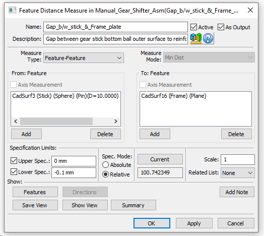
•Name this measurement “Stick and Frame Plate Min Gap ". Give it the description "Minimum gap between Stick bottom ball outer surface to reinforcement plate” (description is not mandatory).
•For Measure Type select Feature-Feature.
•Click [Add] below the From: Feature box list, then select the ball surface of Stick and click [Close] in the Select dialog.
•Click [Add] below the To: Feature list and select the surface on Frame as shown below.
Note: In the Feature Distance Measures it does not matter if a set of features is in the “From” or “To” list.
•For the Specification Limits, uncheck the Upper Spec. box and the set the Lower Spec. to -0.1mm and the Spec Mode to Relative.
•No directions are used in the Feature Distance Measure because the minimum distance between surfaces is always calculated.
•The completed measure dialog should look like the image below.
•Click [OK] to create the measure.
•Save the Model.