First we will look at potential interference between the pins of the Turnlamp and the holes of the Bracket.
•With the Analyst_Tutorial_Lesson6 tab open, Go to the North quadrant of the Compass (called My Social and Collaborative Apps) and select the Collaborative Lifecycle app.
•Select the Analyst_Tutorial_Lesson6 Simulation and select ![]() Duplicate from the toolbar at the bottom.
Duplicate from the toolbar at the bottom.
•Right-click on the new duplicated Analyst_Tutorial_Lesson6 Simulation in the model tree and select Properties.
•In the Reference tab of the Properties dialog, change the Title to "Analyst_Tutorial_Lesson8".
•In the Compass, go to the South Quadrant (called My Content and Simulation Apps) and select 3DCS Variation Analyst V6 in the V+R My Simulation Apps section to return to the 3DCS Variation Analyst workbench.
•Go to File ![]() Save Management.
Save Management.
•Select the Lesson6.CATProduct and select [Save As...].
•In the Save As dialog, rename the Product to "Lesson8.CATProduct" and click [Save].
•In the Save Management dialog select [OK] to save the CATIA Product under its new name. The model is not actually saved until you click OK.
•Click the ![]() Application Button then select
Application Button then select ![]() Save As.
Save As.
•Change the File Name to "Lesson8.wtx".
•Click [Save] in the Save As dialog.
•Go to File ![]() Save As.
Save As.
•In the Save a Copy dialog, enter "Lamp_SubAsm_Lesson8" and make sure the Type is set to Assembly (*.asm). Click [OK].
•In the Assembly Save a Copy dialog, click [Save Copy and Open].
•Close the 3DCS Model Navigator and Creo window for Lamp_SubAsm_Lesson6.
•Click ![]() Update Model in the new window for Lamp_SubAsm_Lesson8.
Update Model in the new window for Lamp_SubAsm_Lesson8.
•Go to File ![]() Save As.
Save As.
•In the Save As dialog, enter "Lamp_SubAsm_Lesson8" as the new File name and make sure the type is set to Part Files (*.prt).
•Click [OK] to save the model and close the Save As dialog.
•Click ![]() Update Model.
Update Model.
•Go to File ![]() Save As.
Save As.
•In the Save as dialog, enter "Lamp_SubAsm_Lesson8" and make sure the Type is set to Assembly.
•Click [Save] to save the model and close the Save As dialog.
•Click ![]() Update Model.
Update Model.
•Click ![]() Nominal Build.
Nominal Build.
•Click ![]() Deviate.
Deviate.
•Zoom in to focus on the O_TurnLp_Clear pin. Notice that in some builds, the Turnlamp pin is crashing through the Bracket (you may need to increase the Delay in the Deviate dialog).
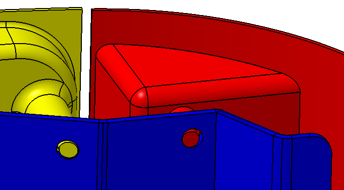
With floating and tolerances, the variation is causing the hole and pin to crash. To validate the model, we will create Circle Interference measures on this pin and hole pair between the Turnlamp and Bracket. The Circle Interference measures will track if there is any interference and the amount of interference.
•Click [Close] in the Deviate dialog.
•Click ![]() Separate.
Separate.
Before creating the Circle Interference measures, we first are going to add points to the Turnlamp and Bracket for the clearance pin-hole pair.
•Following the steps from Lesson 3, create a point at the center of the Turnlamp clearance pin highlights below and name it "O_TurnLp_Clear_Pt".
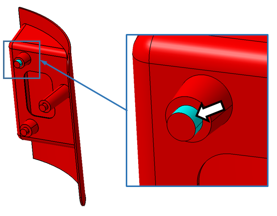
•Again following the steps from Lesson 3, copy the point from Turnlamp to Bracket. Rename the point to "T_TurnLp_Clear_Pt" and then project the point onto its hole feature.
Now that we have the points we need for the Circle Interference measures we can move forward with creating the new measures.
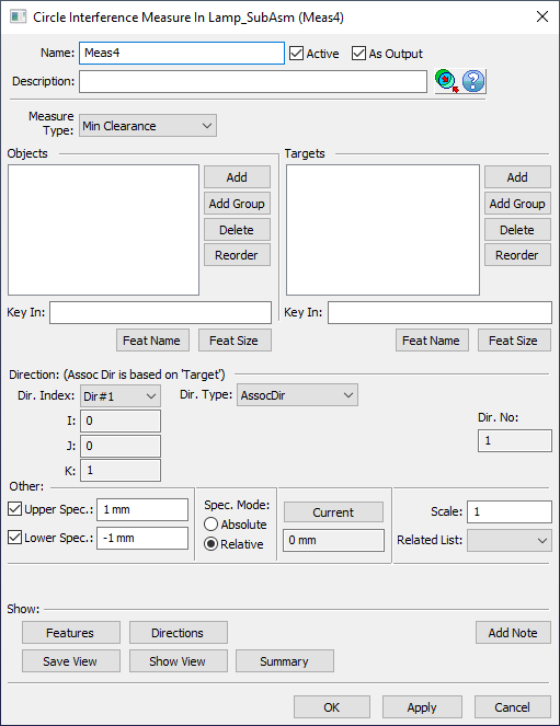
•Click ![]() Measures then select Lamp_SubAsmLamp_SubAsm_Lesson8.
Measures then select Lamp_SubAsmLamp_SubAsm_Lesson8.
•Select Circle Interference from the drop-down list next to [Add].
•Click [Add]. This will open the Circle Interference Measure dialog.
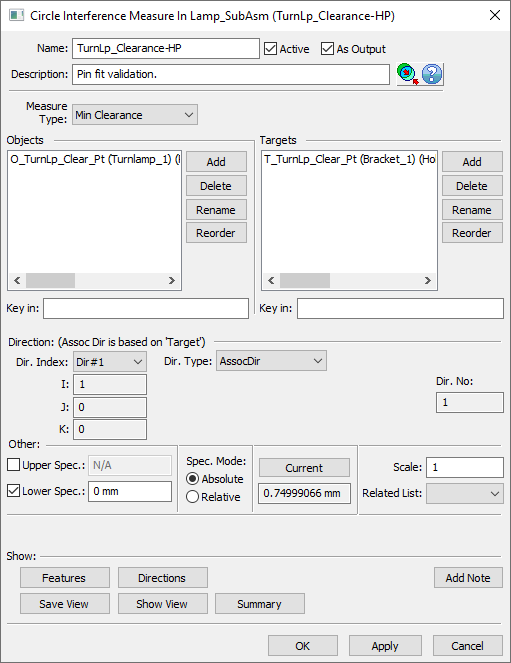
•Change the Name to "TurnLp_Clearance-HP".
•Add a Description of "Pin fit validation.".
•Set the Measure Type to Min Clearance.
•In the Objects section, click [Add] then select the point O_TurnLp_Clear_Pt in the Turnlamp.
•Click [Close] to close the Select dialog.
•In the Targets section, click [Add] then select the point T_TurnLp_Clear_Pt in the Bracket.
•Click [Close] to close the Select dialog.
•Make sure the Dir. Type is set to AssocDir.
•For a clearance measure like this where we only really care to check for interference, we don't need to have an Upper Spec limit. Uncheck the box next to Upper Spec to turn off the upper limit for this measure.
•Any negative number means we have interference, so set the Lower Spec to 0mm.
•Set the Spec. Mode to Absolute.
The completed TurnLp_Clearance-HP measure dialog should look like the image below.
•Click [OK] to save the measure and close the dialog.
•Once the Circle Interference Measure is created, select [OK] to close the Measures dialog.
•Click ![]() Nominal Build then
Nominal Build then ![]() Run Analysis with Recommendation based on convergence on STD enabled.
Run Analysis with Recommendation based on convergence on STD enabled.
•In the Analysis Summary window, double-click TurnLp_Clearance-HP to open the Analysis Results window for the Circle Interference measures.
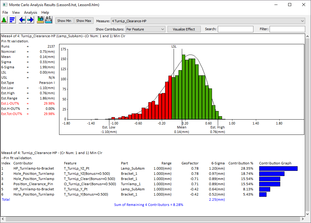
>>> Your results may not match the above illustration <<<
The samples below the lower spec limit (LSL) are the builds that have interference between the pin and hole. We need to modify the model to resolve this crashing that we are currently seeing in the clearance hole for ~30% of samples.
•Close the Analysis windows.
•Click ![]() Separate.
Separate.
•Save the model.