The View Menu allows access to most of the view options in 3DCS. Some of the View menu options are described below.
Visualization in 3DCS is based on a 3-dimensional rectangular or Cartesian coordinate system. In a 3-d Cartesian coordinate system, three coordinate axes are defined at 90 degrees to each other and intersect at a central location called the origin of the coordinate system. Each pair of coordinate axes determines a coordinate plane (i.e. xy-plane, xz-plane, and yz-plane). Cartesian coordinate systems can be either right-handed or left-handed. When a right-handed system is used, the +z-axis is defined by the direction a person's thumb is pointing when the fingers of a person's right hand are cupped so that they curve from the +x-axis to the +y-axis. A left-handed system is similar except that the left-hand is used. The default Cartesian coordinate system used by 3DCS visualization is right-handed, but it can be changed to left-handed without affecting analysis results, it is purely a visualization control.
Procedure:
•Activate the Graphics Window.
•Click on View ![]() Coordinate System
Coordinate System
•Select ![]() Right-Handed (default) or
Right-Handed (default) or ![]() Left-Handed
Left-Handed
This function allows for shadowing of the part on a backplane in the graphics window.
Procedure:
•Activate the Graph Window.
•Click on View ![]() Backplane Culling.
Backplane Culling.
The Cross Section function shows the user the cross section of the model. The cross section can be cut normal to grid, along X, Y, or Z direction.
Procedure:
•Activate the Graph Window.
•Click on View ![]() Cross Section
Cross Section ![]()
![]() X (or
X (or ![]() Y, or
Y, or ![]() Z).
Z).
Notes:
•More than one section plane can be active at a time. The planes can be dragged along the selected direction axis, and rotated around the other two axes.
•The section will stay activated until View ![]() Cross Section is clicked again.
Cross Section is clicked again.
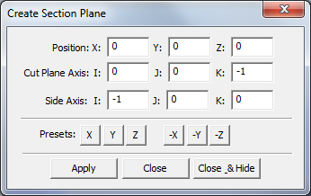
This application allows repositioning the section plane and also reorienting the plane.
•Position - the user can edit the X, Y, Z values to translate the section plane.
•Cut Plane Axis - sets the plane direction (the direction perpendicular to the section plane).
•Side Axis - is used to find the orientation for the plane. To get the third axis use this cross-product: [Side-Axis] X [Cut Plane Axis].

This function shows/hides a section plane in the Graph window. The cross section of the solid parts and the deviated mesh are shown. The plane(s) may be translated and rotated in the Graph window. Manipulating the other options available in the Graphic Properties toolbar will affect the cross section view. New in 6.3.2.
Procedure:
•Activate the Graph Window.
•Click on View ![]() Cross Section
Cross Section ![]()
![]() Show Cross Section Plane, or go to Graphic Properties toolbar and select
Show Cross Section Plane, or go to Graphic Properties toolbar and select ![]() Show Cross Section Plane.
Show Cross Section Plane.
This function shows/hides the manipulator for all cross section planes in the Graph window.
Procedure:
•Activate the Graph Window.
•Click on View ![]() Cross Section
Cross Section ![]()
![]() Cross Section Manipulator, or go to Graphic Properties toolbar and select
Cross Section Manipulator, or go to Graphic Properties toolbar and select ![]() Cross Section Manipulator.
Cross Section Manipulator.
•
Reset X (or Y, or Z)
The reset function will allow the X, Y, or Z cross sections to revert to its default positions.
The Query coordinates function shows the coordinates of a point by clicking in the Graph window.
Procedure:
• Activate the Graph Window.
• Click on View ![]() Query Coordinates
Query Coordinates
• Click in the Graph window
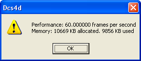
![]() Test Performance - Rotates the object 360 degrees and shows model information such as number of frames per second, allocated memory, and used memory.
Test Performance - Rotates the object 360 degrees and shows model information such as number of frames per second, allocated memory, and used memory.
