For the purposes of this model, we want the Fixture to be at the same level in the assembly as the Lamp_SubAsm. Therefore, we will need to create a new top level productassembly and insert the Lamp_SubAsm into it.
•Highlight the ![]() Insert icon and select Content... The New Content dialog will appear.
Insert icon and select Content... The New Content dialog will appear.
•Select Physical Product from the New Content dialog to create a new Physical Product.
•Right-click on the new Physical Product in the Navigation Tree and select Properties.
•In the Reference tab of the Properties dialog, change the Title to "Final_Assembly".
•Select [OK] to save and close the Properties dialog.
•Right-click on the Final_Assembly and select Insert ![]() Existing Product...
Existing Product...
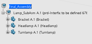
•With the Select dialog open, switch to the Lamp_SubAsm tab and select the Lamp_SubAsm Product.
•Select the Green Check Mark in the Select dialog (dialog will have automatically disappeared if Multiselection is not active) to add the Lamp_SubAsm to the Final_Assembly Product.
Next, a new part to act as the fixture for the Lamp_SubAsm. Right-Click on the top assembly in the Navigation Tree, and highlight [Insert] ![]() [3D Part]
[3D Part]
•Right-click on the Final_Assembly and select Insert ![]() 3D Part.
3D Part.
•Right-click on the new 3D Part in the Navigation Tree and select Properties.
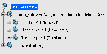
•In the Reference tab of the Properties dialog, change the Title to "Fixture".
•In the Instance tab of the Properties dialog, change the Instance Title to "Fixture".
•In the Reference tab of the Properties dialog, change the Title to "Fixture".
•Select [OK] to save and close the Properties dialog.
By changing our highest Product level from Lamp_SubAsm 3DEXPERIENCE has left the Review and individual part properties at the sub-assembly level and they can no longer be accessed at the Final_Assembly level. If desired, we must return to the Final_Assembly Product tab and recreate the Review and change the part colors using the same methods covered in Lesson 2.
•Return to the Final_Assembly Product tab.
•Repeat the procedure done in Lesson 2 to apply the correct colors to the Bracket, Turnlamp, and Headlamp.
•In the North Quadrant of the compass, select the Design Review icon to open the Design Review app.
•A Review with a Markup will automatically be added to the Model Tree for Final_Assembly.
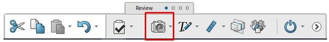
•In the Review toolbar (now the displayed toolbar at the bottom of the screen) select the Slide icon to add a new slide to the Markup.
•Right-click the new slide and select Properties to open the Properties dialog. Change the Feature Name to "Nominal" and select [OK].
•Separate the Turnlamp and Headlamp from the Bracket using the same procedure used in Lesson 2.
•By dragging the Compass direction, drag the Lamp_SubAsm about 200 mm away from the Fixture in the X direction.
•Return the Compass to the corner.
•Create a slide for this separated position. Name the slide "Exploded".
Now that the product tree is structured as desired and we've recreated our slides. We will need to update the 3DCS model.
•With the Final_Assembly tab open, create a new Manufacturing Simulation.
•Right-click on the new Simulation in the Navigation Tree and select Properties.
•In the Reference tab of the Properties dialog, change the Title to "Analyst_Tutorial_Lesson10".
•Switch the app to 3DCS Variation Analysis if not already there.
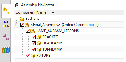
Your Navigation Tree should now look like the following image.
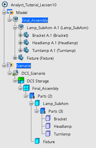
Notice that our 3DCS data did not come over when the Lamp_SubAsm was brought into our Final_Assembly model. This is because that data was stored at the Simulation level, not at the Product level, so our new Simulation has no 3DCS data. The 3DCS data can be restored by importing the WTX file we exported at the end of Lesson 6.
•Select ![]() Import from the 3DCS Tools section of the toolbar.
Import from the 3DCS Tools section of the toolbar.
•In the Import dialog navigate to the Anayst_Tutorial_Lesson6.wtx file that was exported at the end of Lesson 6.
•With Analyst_Tutorial_Lesson6.wtx selected, click [Open] import the WTX file.
•If prompted, select the Lamp_SubAsm sub-product in the Navigation Tree.
•Select [Merge: Add and Update] from the Lamp_SubAsm_A_1 dialog.
A warning message will appear to alert the user of lost feature links. When information is 3DCS data is imported in through a WTX, 3DCS is able to put the mesh and points in the correct coordinate location, but 3DCS cannot attach it to the actual CAD geometry so the user needs to tell 3DCS which features are associated to the CAD geometry.
•Select [Close] in the Lost Feature Links dialog.
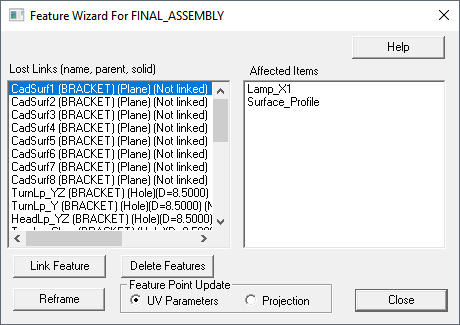
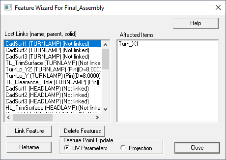
•Click ![]() Feature Wizard. This will open the Feature Wizard For Final_Assembly dialog.
Feature Wizard. This will open the Feature Wizard For Final_Assembly dialog.
In the Feature Wizard dialog, the user can relink the Features in 3DCS to line up with Features on the actual CAD geometry. When a Feature is selected from the Lost Links list of the Feature Wizard dialog it is highlighted in the Graphics Window to help the user correctly relink the 3DCS Features.
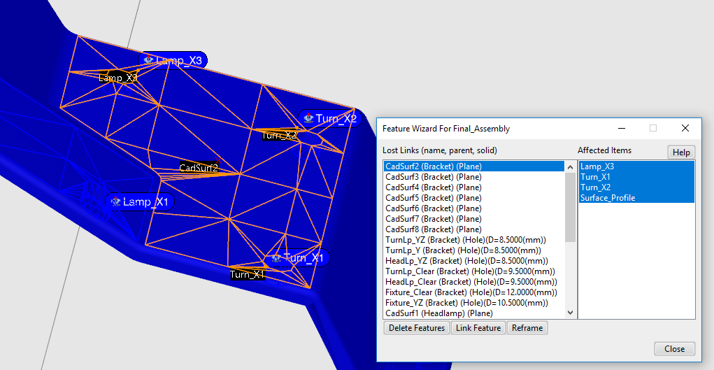
•Select the first feature in the Lost Links list.
•Click [Link Feature] then, in the graphics area, select the CAD geometry surface that corresponds to the 3DCS feature.
•Repeat this process for all features in the Lost Links list. If a feature has an empty Affected Items list, click [Delete Feature].
•Once all of the features have been linked (or deleted), click [Close].
•Click [OK] to close the notification about all features linked.
•Save the model.
First, we need to save the 3DCS data for the model through Lesson 6.
•Open the saved model Lamp_SubAsm_Lesson6.
•Click ![]() Update Model.
Update Model.
•Leave this model open as we will need it for a future part of this lesson.
Now, we will create a new assembly and add the Fixture.
•Go to File ![]() New and in the New SOLIDWORKS Document dialog select Assembly.
New and in the New SOLIDWORKS Document dialog select Assembly.
•In the Begin Assembly dialog, select [Browse...].
•Select Lamp_SubAsm_Lesson6.sldasm and click [Open].
•Select ![]() OK in the Begin Assembly tab to place Lamp_SubAsm_Lesson6 at the origin.
OK in the Begin Assembly tab to place Lamp_SubAsm_Lesson6 at the origin.
•From Assembly tab select New Part under Insert Components.
•Right-click on the newly created part and select Rename Part and enter "Fixture" as the new part name.
•Go to File ![]() Save As.
Save As.
•In the Save As dialog, enter "Final_Assembly" for the File Name, make sure the Type is set to Assembly.
•Click [Save] in the Save As dialog.
•If prompted, select Save internally (inside the assembly) and then select [OK].
•Right click the Assembly and select Document Properties and go down to Units and select MMGS (millimeter, gram, second) then select [OK].
Next we need to add an Exploded View to the Final_Assembly.
•Select Configuration Manager from the toolbar on the left hand side of the screen.
•Right-click on Default from the tree under Configurations and select New Exploded View...
•In the tree that is overlaid on the Graphics Window select Lamp_SubAsm_Lesson6.
•In the Graphics Window, click and drag the arrow labeled X on the compass to move the Lamp_SubAsm_Lesson6 in the negative X direction by 100mm.
•In the Explode dialog on the left of the screen, select [Done] to complete Explode Step1.
Next we can copy the steps from the Lamp_SubAsm_Lesson6 sub-assembly.
•In the tree that is overlaid on the Graphics Window select Lamp_SubAsm_Lesson6.
•In the Explode dialog select [Reuse Subassembly Explode].
•Select ![]() OK in the Explode dialog to complete and save the newly created Exploded View.
OK in the Explode dialog to complete and save the newly created Exploded View.
The Bracket, Headlamp, and Turnlamp should all be separated from each other again. Now, we will import the 3DCS data for Lamp_SubAsm_Lesson6.
•In the 3DCS Variation Analyst tab, click ![]() Update Model. Notice that in the new Model Navigator we currently have none of the 3DCS data that used to exist within Lamp_SubAsm_Lesson6 and its parts.
Update Model. Notice that in the new Model Navigator we currently have none of the 3DCS data that used to exist within Lamp_SubAsm_Lesson6 and its parts.
•Click the drop down under ![]() Import and select
Import and select ![]() Import Subassembly. Select Lamp_SubAsm_Lesson6. This function will only work if the Lamp_SubAsm_Lesson6 is currently open. This is why we left it open previously.
Import Subassembly. Select Lamp_SubAsm_Lesson6. This function will only work if the Lamp_SubAsm_Lesson6 is currently open. This is why we left it open previously.
•Click [Merge: Add and Update].
•Click [OK] in the Lost Feature Links dialog.
Importing a Subassembly brings in 3DCS data but it does not keep the links to the SW CAD geometry. We can easily use the Auto Link function to relink the lost links to the CAD.
• Click ![]() Feature Wizard. This will open the Feature Wizard For Final_Assembly dialog.
Feature Wizard. This will open the Feature Wizard For Final_Assembly dialog.
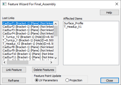
•Click [Auto Link]. This will automatically link all the lost feature links to their respective CAD.
•Click [Close].
•Select File ![]() Save, navigate to your working directory if not already there, then click [OK] in the Save Object dialog.
Save, navigate to your working directory if not already there, then click [OK] in the Save Object dialog.
First, we need to save the 3DCS data for the Lamp_SubAsm.
•Open the saved model Lamp_SubAsm_Lesson6.
•Click ![]() Update Model.
Update Model.
•Close the model Lamp_SubAsm_Lesson6.
Now, we will create a new assembly and add the Fixture.
•Go to File ![]() New
New
•Select Assembly for the Type and Design for the Sub-type.
•Change the Name to "Final_Assembly" then click [OK].
•Select File ![]() Prepare
Prepare ![]() Model Properties.
Model Properties.
•Under Materials, click change to the right of Units.
•In the Units Manager dialog, select millimeter Newton Second (mmNs) then click [Set...].
•In the Changing Model Units dialog, in the Model tab, select Convert dimensions then click [OK].
•Click [Close] in the Units Manager dialog then click [Close] in the Model Properties dialog.
•In the Model tab, click the ![]() Assemble button.
Assemble button.
•Open Lamp_SubAsm_Lesson6.asm.
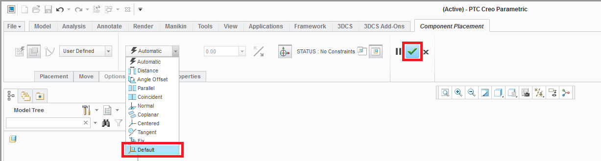
•In the Component Placement tab, select [Default] in the Relationship Type drop-down list.
•Click the Green Check Mark.
•Click the [Create] button.
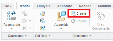
•In the Create Component dialog, select Part for the Type and Solid for the Sub-type.
•Enter the Name as "Fixture" then click [OK].
•In the Creation Options dialog, choose Empty for the Creation Method, keep Leave component unplaced unchecked, then click [OK].
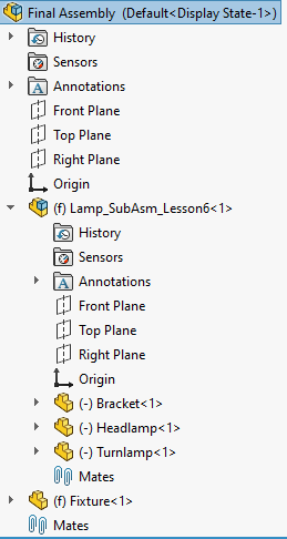
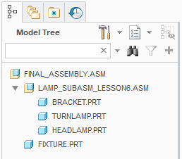
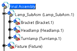
Your Model Tree should like the following image.
Unfortunately, the exploded view we created earlier is not saved when inserting into the Final_Assembly so we will create a new exploded view. Refer back to Lesson 2 if needed.
•Click ![]() Manage Views.
Manage Views.
•In the View Manager dialog, select the Explode tab and click [New].
•Type "Exploded" as the name and press the Enter key to create the exploded view.
•With Exploded highlighted, click [Edit] then select Edit Position.
•In the Creo Model Tree, select the Lamp_SubAsm_Lesson6.
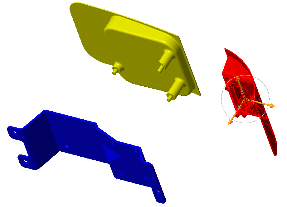
•Drag the compass arrow to move Lamp_SubAsm_Lesson6 about -100 mm in the X-direction away from the Fixture (which is empty so it is invisible).
•In the Creo Model Tree, select only the Turnlamp and the Headlamp.
•Drag the compass arrow of the compass to move Turnlamp and Headlamp about -200 mm in the X-direction away from the Bracket.
•Select only the Turnlamp.
•Drag the compass to move the Turnlamp about 100 mm in the Y-direction away from the Headlamp. Your model should look similar to the previous exploded view from Lesson 2.
•Click the Green Check Mark in the Explode Tool tab.
•Click [Edit] then select Save... .
•In the Save Display Elements dialog, make sure Explode is checked and Exploded is selected from the drop-down list, then click [OK].
•Click [Close] in the View Manager dialog.
Now, we will import the 3DCS data for the Lamp_SubAsm.
•In the 3DCS tab, click ![]() Update Model.
Update Model.
•Click the drop down under ![]() Import and select
Import and select ![]() Import Subassembly. Select Lamp_SubAsm_Lesson6. This function will only work if the Lamp_SubAsm_Lesson6 is currently open. This is why we left it open previously.
Import Subassembly. Select Lamp_SubAsm_Lesson6. This function will only work if the Lamp_SubAsm_Lesson6 is currently open. This is why we left it open previously.
•Click [Merge: Add and Update].
•Click [OK] in the Lost Feature Links dialog.
Importing a Subassembly brings in 3DCS data but it does not keep the links to the Creo CAD geometry. We can easily use the Auto Link function to relink the lost links to the CAD.
• Click ![]() Feature Wizard. This will open the Feature Wizard For Final_Assembly dialog.
Feature Wizard. This will open the Feature Wizard For Final_Assembly dialog.
•Click [Auto Link]. This will automatically link all the lost feature links to their respective CAD.
•Click [Close].
•Select File ![]() Save, navigate to your working directory if not already there, then click [OK] in the Save Object dialog.
Save, navigate to your working directory if not already there, then click [OK] in the Save Object dialog.
•Click the ![]() Application Button then select
Application Button then select ![]() New.
New.
•In the Navigation Tree, double-click Root. Change the Name to "Final_Assembly" then click [OK].
•Click ![]() Import 3DCS File.
Import 3DCS File.
•Select your saved Lesson6.wtx and click [Open].
•In the 3DCS dialog, click [No] to append the Lamp_SubAsm from Lesson6 under the new Final_Assembly.
•![]() Nominal Build and
Nominal Build and ![]() Deviate to verify the data imported correctly.
Deviate to verify the data imported correctly.
•Close the Deviate dialog and click ![]() Separate.
Separate.
•In the Navigation Tree, right-click Final_Assembly then select Parts ![]()
![]() Create Parts.
Create Parts.
•In the Navigation Tree, double-click the newly created part. Change the Name to "Fixture", check the Fixture setting, uncheck Default Color, and click [OK].
When the Fixture setting is checked for a part, it will not move during the assembly process unless it is specifically added to the Move Parts list. Your tree should look like the following image.
We will translate the Lamp_SubAsm away from the Fixture to see the subassembly move.
•Right-click Lamp_SubAsm in the tree and select ![]() Translate/Rotate.
Translate/Rotate.
•Set the drop-down lists to Translate and X-Axis. Set the Step to 100.
•Click [Decrease] to translate the Lamp_SubAsm -100 mm in the X-direction.
•Click [Close] in the Translate/Rotate dialog.
•Click the ![]() Application Button then select
Application Button then select ![]() Save As.
Save As.
•Change the File Name to "Lesson10.wtx".
•Click [Save] in the Save As dialog.
•Create a new product file using File ![]() New... then select Product and [OK].
New... then select Product and [OK].
•Right-click on the new Product in the Navigation Tree and select Properties.
•Change the Part Number of the new product to "Final Assembly" and select [OK] to exit the Properties dialog.
•Right-click Final Assembly in the Navigation Tree and go to Components ![]() Existing Component....
Existing Component....
•Select your saved Lesson6.CATProduct then click [Open].
This will insert the completed Lesson6 model into the new product, including all 3DCS modeling data (the 3DCS data will be shown later after ![]() Update Model). We will now create a new part to represent the fixture.
Update Model). We will now create a new part to represent the fixture.
•Right-click Final_Assembly in the Navigation Tree and go to Components ![]() New Part.
New Part.
•Click [No] in the New Part: Origin Point dialog to define the origin point of the assembly as the new part origin point.
•Right-click the new part in the Navigation Tree and select Properties.
•In the Product tab, change the Instance Name to "Fixture" and the Part Number to "Fixture".
•Click [OK]. Your Navigation Tree should look like the image below.
Note: The Fixture is an empty CATIA part file that will only contain 3DCS data. Therefore, no geometry will appear on your screen.
•Click ![]() Update Model.
Update Model.
•Go to Save Management.
•Select the new Final Assembly.CATProduct and [Save As] "Lesson10.CATProduct".
•Select the modified Lesson6.CATProduct and [Save As] "Lesson10Sub.CATProduct".
Note: We do not want changes made to the Lamp_SubAsm Product to change the data that is already stored in Lesson6.CATProduct so we save a copy of Lesson6.CATProduct as Lesson10Sub.CATProduct. This is an uncommon practice when building a 3DCS model using real geometry. Typically you will want to maintain reference to the original geometry and won't want to save a copy of any subassembly or part..
•Click [OK].
Before we create the points in the Fixture, we will translate the Lamp_SubAsm away from the Fixture.
•Drag the Compass by the red square onto the Bracket.
•Select the Lamp_SubAsm in the Navigation Tree so that the Bracket, Headlamp, and Turnlamp will all translate together (the Compass should be green).
•Drag the Compass ~100 mm in the -X direction to translate the parts.
•Drag the Compass into the lower right hand corner to reset the compass to its original position in the top right corner.
•Click ![]() Update Model.
Update Model.
•Open the saved model Lamp_SubAsm_Lesson6.
•Click ![]() Load 3DCS.
Load 3DCS.
•Click ![]() Update Model. We will need this model open for a future section of this lesson.
Update Model. We will need this model open for a future section of this lesson.
•In NX, switch to the Assemblies tab and click ![]() Create New Parent.
Create New Parent.
•Select Assembly and change the Name to "Final_Assembly".
•Select your working directory for the Folder then click [OK].
•In the Assemblies tab click ![]() Create New.
Create New.
•Select Model and change the name to "Fixture".
•Select your working directory for the Folder then click [OK].
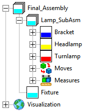
•In the Create New Component dialog, set the Component Origin to Absolute then click [OK]. Your tree should look like the image below.
We will create a new exploded arrangement for the Final_Assembly. Refer back to Lesson 2 for more information on creating assemblies and translating parts, if needed.
•Right-click Lamp_SubAsm_Lesson6 in the Assembly Navigator and select Properties.
•In the Parameters tab, in the Parameters section, select Individually Positioned.
•Click [OK] to close the Component Properties dialog.
•Repeat the previous three steps to set the Fixture as Individually Positioned.
•Right-click Lamp_SubAsm_Lesson6 and select Arrangements ![]() Design to reset the Headlamp and Turnlamp positions if not already there.
Design to reset the Headlamp and Turnlamp positions if not already there.
•Right-click Final_Assembly and select Arrangements ![]() Edit...
Edit...
•Select Arrangement 1 (Default) and click ![]() Rename. Rename the arrangement "Design".
Rename. Rename the arrangement "Design".
•Click ![]() New Arrangement and name it "Exploded".
New Arrangement and name it "Exploded".
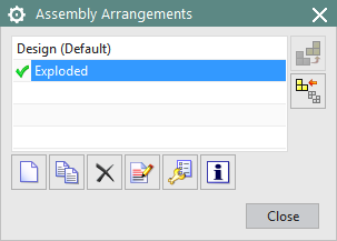
•With the Exploded arrangement still selected, click ![]() Use. The completed Assembly Arrangements dialog should look like the image below.
Use. The completed Assembly Arrangements dialog should look like the image below.
•Click [Close] in the Assembly Arrangements dialog.
•Right-click on Lamp_SubAsm_Lesson6 in the Assembly Navigator and select the ![]() Move icon.
Move icon.
•In the Transform section, select Dynamic for the Motion type.
•Drag the XC arrow of the trihedron to translate the subassembly -150 mm in the x-direction.
•Click [<OK>] in the Move Component dialog.
•Right-click Lamp_SubAsm_Lesson6 and select Arrangements ![]() Exploded.
Exploded.
•Save the model.
Now we will import the saved 3DCS data into the subassembly.
•Switch to the 3DCS tab.
•Click ![]() Update Model.
Update Model.
•Click the drop down under ![]() Import (it may be under
Import (it may be under ![]() Export) and select
Export) and select ![]() Import Subassembly. Select Lamp_SubAsm_Lesson6. This function will only work if the Lamp_SubAsm_Lesson6 is currently open. This is why we left it open previously.
Import Subassembly. Select Lamp_SubAsm_Lesson6. This function will only work if the Lamp_SubAsm_Lesson6 is currently open. This is why we left it open previously.
•Click [Merge: Add and Update].
•Click [OK] in the Lost Feature Links dialog.
•Click ![]() Update Model and close the warning about lost links if it comes up again.
Update Model and close the warning about lost links if it comes up again.
Importing a Subassembly brings in 3DCS data but it does not keep the links to the NX CAD geometry. We can easily use the Auto Link function to relink the lost links to the CAD.
• Click ![]() Feature Wizard. This will open the Feature Wizard For Final_Assembly dialog.
Feature Wizard. This will open the Feature Wizard For Final_Assembly dialog.
•Click [Auto Link]. This will automatically link all the lost feature links to their respective CAD (if not all features are linked then either manually link the features or try Auto Link again).
•Click [Close].
•Save the model.