The features of the Fixture are assumed to have identical coordinates as the Bracket. To create them, we will create the features on the Bracket and copy them to the Fixture. Since feature mesh cannot be copied, we will create Feature Points on the Bracket to represent the mounting features. Three surface feature points and two hole feature points will be needed on the Bracket.
•Create three Feature Points on the surfaces of the Bracket and name them "O_Fixture_X1", "O_Fixture_X2" and "O_Fixture_X3" according to the image below.

•Create a point at the Center of the hole feature O_Fixture_YZ in the Bracket and name the point "O_Fixture_YZ_Pt".
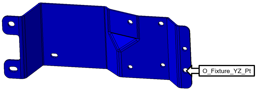
To get a point at the center of the Bracket's slot we will have to do a little more work. We will use the two half cylinders of the slot and a dynamic midpoint to create the final point needed for the Fixture.
•Create two points in the Bracket's large slot, one at the Center of each of the half cylinders as shown below.
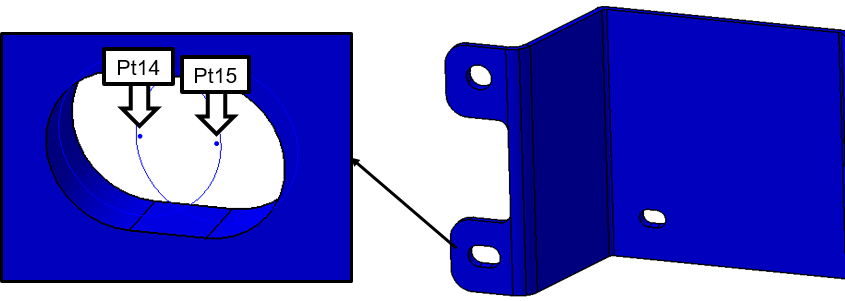
•Click the ![]() Dynamic Point button then click [Create].
Dynamic Point button then click [Create].
•Select the two points you just created in the slot.
•Set the Dynamic Scale to 0.5.
•Click [OK]. You should have a Dynamic Midpoint as shown below.
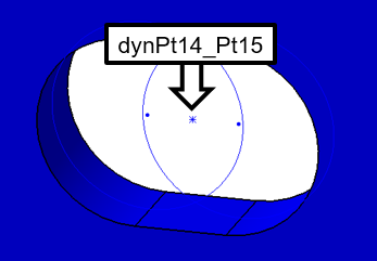
•Change the name of the Dynamic Midpoint to "O_Fixture_Z_Pt".
We now have all of the points necessary to create the Fixture. We will use a different method to copy the points from the Bracket to the Fixture.
•Click ![]() Points and select the Fixture to open up the Points dialog for the Fixture.
Points and select the Fixture to open up the Points dialog for the Fixture.
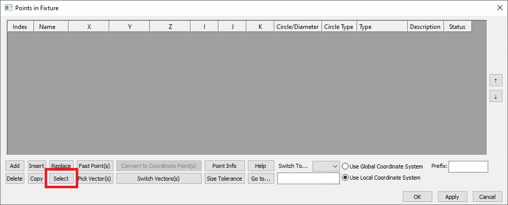
•In the Points dialog, verify that Local coordinate system is selected in the lower right for Point copying method:. Then click [Select] (shown below) to open the Select dialog. With the Select dialog open, any point in 3DCS selected will copy to the Fixture.
•Select point O_Fixture_X1 in the Bracket and select [Yes] in the 3DCS dialog to copy the point into the Fixture point list using the Local Coordinate System.
•With the Select dialog still open, copy O_Fixture_X2, O_Fixture_X3, O_Fixture_YZ_Pt, and O_Fixture_Z_Pt into the Fixture point list too following the same steps.
•Select [Close] in the Select dialog to return to the Points dialog for the Fixture. The Points dialog should now look like the image below.
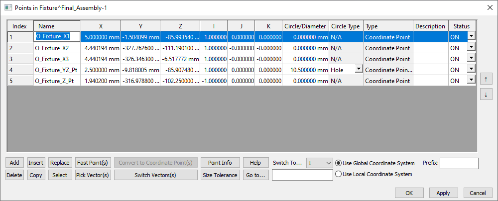
•Select [OK] to save and close the Points dialog.
We no longer need three of the points in the Bracket. We will delete them to clean up the model.
•Click ![]() Points and select the Bracket.
Points and select the Bracket.
•Select O_Fixture_Z_Pt and the two points used to create the Dynamic Point (14 and 15Pt14 and Pt15 in the image above) then click [Delete].
•Click [OK] to close the Points dialog.
•Also select the two new round features used to create the points for the Dynamic Point from the 3DCS Model Navigator and delete these Features as well.
Next we will use the ![]() Find/Replace tool to quickly update the names of the points in the Fixture.
Find/Replace tool to quickly update the names of the points in the Fixture.
•Select ![]() Find/Replace to open the Find/Replace dialog.
Find/Replace to open the Find/Replace dialog.
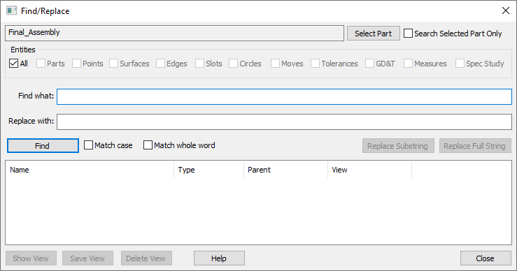
•Select [Select Part] and select the Fixture from the 3DCS Model Navigator.
•In the Find what: text entry field type in "O_" (without the quotation marks) and select [Find]. Notice that all occurrences of "O_" within the Fixture part are shown in the table at the bottom of this dialog.
•In the Replace with: text entry field type in "T_" (again, without the quotation marks).
•Hold Ctrl and select all five of the points shown in the table at the bottom of the Find/Replace dialog.
•Select [Replace Substring]. All occurrences of "O_" should now be replaced with "T_" within the Fixture.
•Select [Close] to exit the Find/Replace dialog.
The Points section for the Fixture in the tree should now look like the following image.
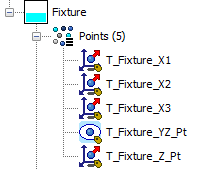
Two of the Fixture points need to be modeled as Pins and given the correct Diameter.
•Click ![]() Points and select the Fixture.
Points and select the Fixture.
•Select the point T_Fixture_YZ_Pt and change the Circle/Diameter to 10mm.
•Set the Circle Type to Pin.
•Select the point T_Fixture_Z_Pt and change the Circle/Diameter to 10mm.
•Click [Apply] for 3DCS to recognize the size change.
•Set the Circle Type to Pin.
The Points dialog for the Fixture should be similar to the image below.
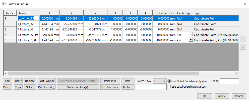
•Select [OK] to close the Points dialog.
•Save the model.