Bonus Tolerance through MMC or LMC in the Feature Control Frame is supported in 3DCS. The supported GD&T types for Bonus Tolerance are ![]() Position,
Position, ![]() Flatness,
Flatness, ![]() Perpendicularity,
Perpendicularity, ![]() Angularity,
Angularity, ![]() Parallelism, and
Parallelism, and ![]() Straightness. The
Straightness. The ![]() Circular Tolerance also supports Bonus Tolerance. This section will go over how to apply a Bonus Tolerance to a GD&T or Tolerance in 3DCS and how 3DCS simulates it.
Circular Tolerance also supports Bonus Tolerance. This section will go over how to apply a Bonus Tolerance to a GD&T or Tolerance in 3DCS and how 3DCS simulates it.
Adding Bonus to GD&T Procedure:
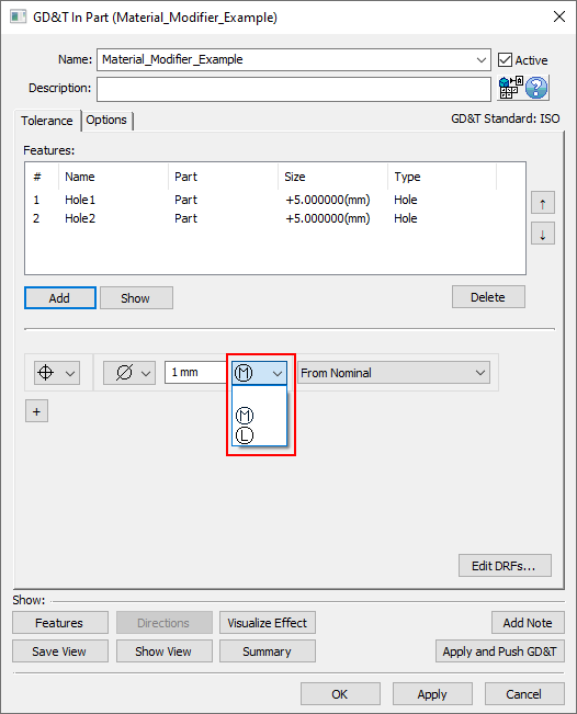
1.In the GD&T dialog for an applicable GD&T, simply select the drop-down following the Range and select ![]() for MMC,
for MMC, ![]() for LMC, or leave it blank for RFS. Note: The Material Modifier drop-down menu will only be available for supported GD&T types.
for LMC, or leave it blank for RFS. Note: The Material Modifier drop-down menu will only be available for supported GD&T types.
Adding Bonus to Circular Tolerance Procedure:
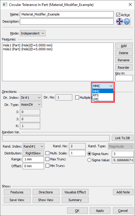
1.In the Circular Tolerance dialog, select the drop-down to the lower-right of the Features list and select MMC, RFS, or LMC.
Applying the Size GD&T or Tolerance Correctly:
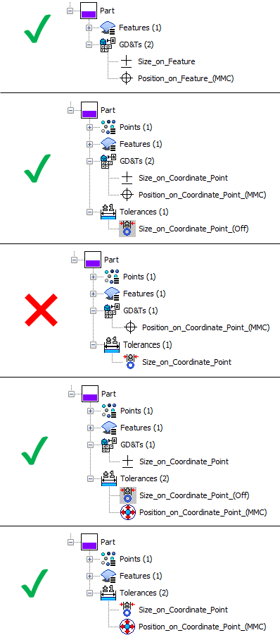
It's important to note that it is possible for the size variation to not be taken into account in the tolerance. The only time that size will not be taken into account correctly for bonus is when the Bonus Tolerance is applied to a GD&T (an ![]() modifier in a
modifier in a ![]() Position GD&T for example) and the size variation is applied as a
Position GD&T for example) and the size variation is applied as a ![]() Size Tolerance on a Coordinate Point. All other cases will take the size into account correctly when calculating bonus. The image below sums up five possibilities showing the only one that doesn't work. If a Coordinate Point is being used with GD&T that contains a Material Modifier, then it is recommended to turn off the variation from the
Size Tolerance on a Coordinate Point. All other cases will take the size into account correctly when calculating bonus. The image below sums up five possibilities showing the only one that doesn't work. If a Coordinate Point is being used with GD&T that contains a Material Modifier, then it is recommended to turn off the variation from the ![]() Size Tolerance and rather create a
Size Tolerance and rather create a ![]() Size GD&T for the Coordinate Point.
Size GD&T for the Coordinate Point.
How Bonus Tolerance Deviates - Monte Carlo:
In a Monte Carlo analysis, the bonus is calculated in a few steps:
1.Vary the size of the Feature of Size (based on Range and Distribution for the size input.
2.Calculate how much Bonus Tolerance to include in the specific GD&T or ![]() Circular Tolerance.
Circular Tolerance.
3.Add the calculated Bonus Tolerance to the Range of the specific GD&T or ![]() Circular Tolerance.
Circular Tolerance.
4.Using the newly calculated Range, apply the specific GD&T or ![]() Circular Tolerance variation for this build.
Circular Tolerance variation for this build.
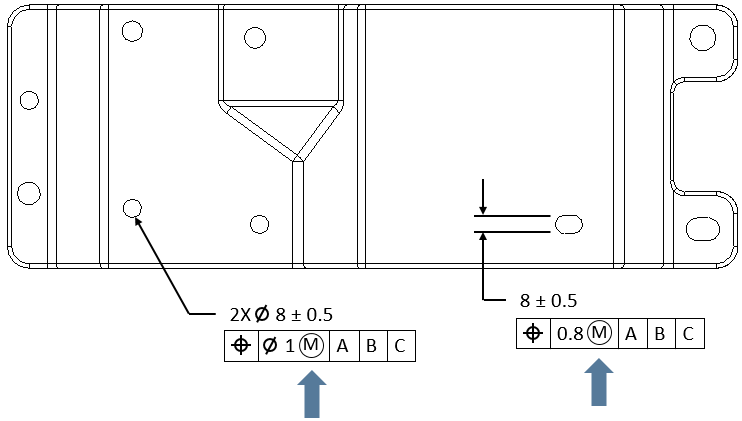
This procedure can best be explained with an example. For the example we will use this ![]() Position GD&T on a slot:
Position GD&T on a slot:
1.Vary the size of the Feature of Size: for this build the slot is 8.25mm.
2.Calculate how much Bonus Tolerance: 8.25mm (Actual Size) - 7.5mm (MMC Slot Size) = 0.75mm.
3.Add the calculated Bonus Tolerance to the Range: 0.75mm (Calculate Bonus) + 0.8mm (MMC Range) = 1.55mm.
4.Use the newly calculated Range: for this build the slot can be anywhere in ±0.775mm from Nominal.
How Bonus Tolerance Impacts Statistics - Monte Carlo:
Because Bonus Tolerance is a combination of two different inputs, it may be unlikely for the measured distribution of the location of the feature (if it is a location input that has the bonus tolerance applied to it) to match the input distribution, particularly if the Range of the size is much larger than the Range of the location.
Here are two examples: one where the location range is much larger than the size range and one where the size range is much larger than the location range. In each example the results are shown for a measure checking the position of the center plane of the slot.
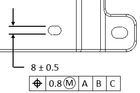
Example of a call out where the MMC range is much larger than the potential Bonus tolerance.
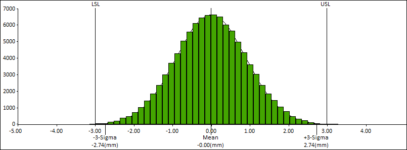
The results when the MMC range is much larger than the potential Bonus tolerance appear to be a pretty standard Normal Distribution with just slightly longer tails than may be anticipated if Bonus tolerance was not present.
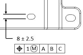
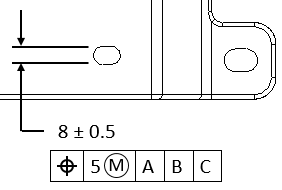
Example of a call out where the MMC range is much smaller than the potential Bonus tolerance.
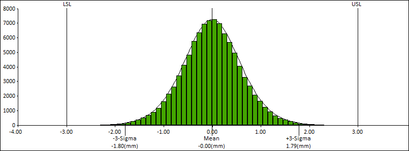
The results when the MMC range is much smaller than the potential Bonus tolerance appear to be a distribution with a much sharper center and much longer tails than may be anticipated if Bonus tolerance was not present.
How Bonus Tolerance Deviates - GeoFactor Equation-Based & Contributor Analysis:
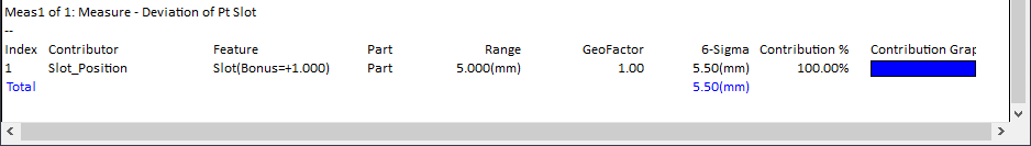
Because the GeoFactor Equation-Based Analysis and Contributor Analysis are only checking one variable at a time and are not operating on a per build basis, 3DCS applies a scaling factor to the Range used based on the associated Size variation to the Feature. In the Contributor Analysis results, the displayed range in the Range column will display the MMC (or LMC) range but in the N-Sigma column, it will display a larger value than anticipated because it is taking the Bonus tolerance scaling factor into account. Also, when set to Per Feature, the Feature column will display the maximum amount of bonus per each feature. This is shown in the images below.
Using the same examples from above, here are the GeoFactor Equation-Based Analysis results and Contributor Analysis results.
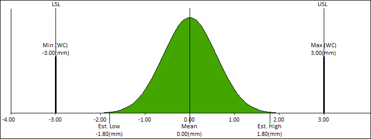
Example of a call out where the MMC range is much larger than the potential Bonus tolerance.
The GeoFactor Equation-Based results when the MMC range is much larger than the potential Bonus tolerance.
The Contributor results showing the Bonus in the Feature column and the adjusted range in the 6-Sigma column.
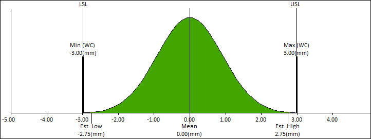
Example of a call out where the MMC range is much smaller than the potential Bonus tolerance.
The GeoFactor Equation-Based results when the MMC range is much smaller than the potential Bonus tolerance.
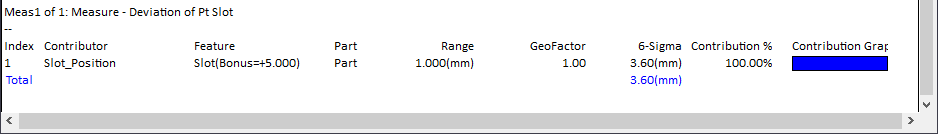
The Contributor results showing the Bonus in the Feature column and the adjusted range in the 6-Sigma column.
Composite Position GD&T at MMC or LMC
For information about Bonus tolerance and Composite Position GD&T, see Composite Position GD&T at MMC or LMC.
Truncation with Bonus Tolerance
The truncation values are adjusted on a per build basis to take the allowable bonus tolerance into account. This concept is best explained with an example. For the following combination of ![]() Size and
Size and ![]() Position the truncation values are shown for a few different possible builds. For this example, the feature is a hole and the truncation in the 3DCS dialog will be set at +0.5 and -0.5.
Position the truncation values are shown for a few different possible builds. For this example, the feature is a hole and the truncation in the 3DCS dialog will be set at +0.5 and -0.5.
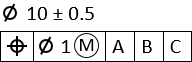
Example of a callout on a hole with Size and Position with MMC.
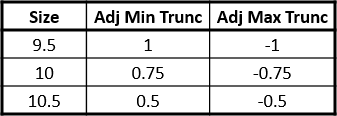
Different Adjusted Trunc values for different Sizes of the hole.