Within a ![]() Surface Profile or
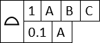
Surface Profile or ![]() Position GD&T in 3DCS Variation Analyst it is possible to apply a Composite GD&T as may be seen on the drawing like this:
Position GD&T in 3DCS Variation Analyst it is possible to apply a Composite GD&T as may be seen on the drawing like this:
To switch a ![]() Surface Profile or
Surface Profile or ![]() Position GD&T to a Composite GD&T, simply select [Make Composite] shown below when the correct GD&T is active in the window:
Position GD&T to a Composite GD&T, simply select [Make Composite] shown below when the correct GD&T is active in the window:
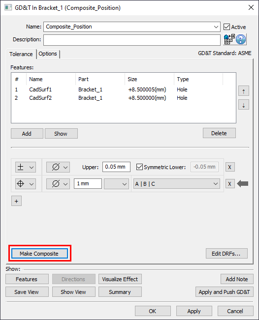
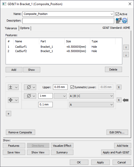
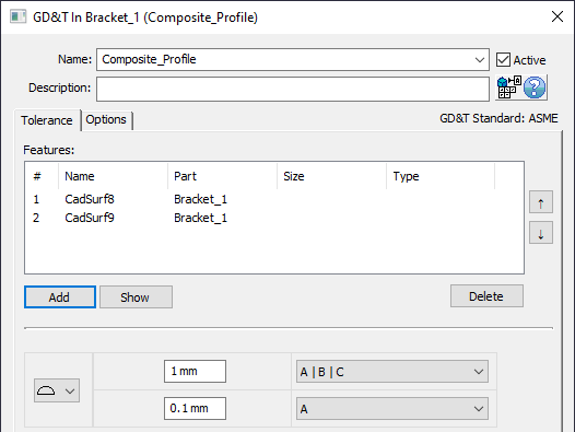
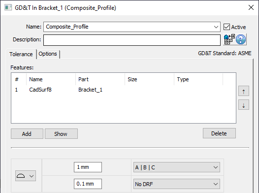
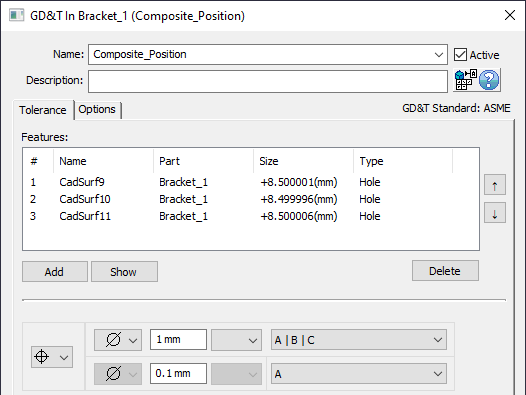
Following selecting this button the dialog will change and there will now be two lines for this GD&T:
In ASME, the terms for the upper frame and lower frame are Pattern Locating Tolerance Zone Framework (abbreviated to PLTZF) and Feature Relating Tolerance Zone Framework (abbreviated to FRTZF) respectively, therefore, those will be the terms used throughout the following descriptions.
Applying a Composite Surface Profile GD&T
There are three possible ways to apply a Composite Surface Profile GD&T within 3DCS Variation Analyst:
1.Two or more features selected in the Features section:
If two or more features are selected within the Features section of the GD&T dialog, then the group of features are treated as a pattern of faces. They will vary independently within the zone allowed by the FRTZF and they will vary as a group within the zone of the PLTZF. An adjustment is made to the value of the amount of variation allowed for the PLTZF such that when both inputs are Normal Distributions, the two variations RSS together to form a Normal Distribution which statistically does not exceed the allowable boundary of the PLTZF.
The PLTZF and FRTZF are shown below for the two generic faces that the Composite Surface Profile GD&T was applied to. An example of 1 possible deviation is also shown:
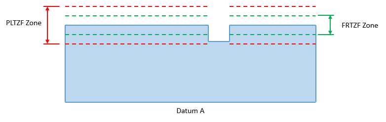
Above: PLTZF and FRTZF zones for the geometry at Nominal
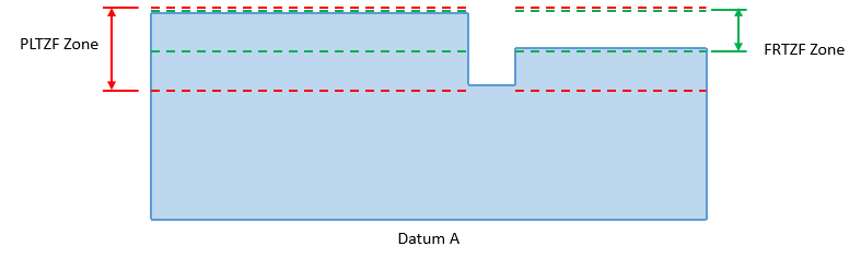
Above: PLTZF and FRTZF zones for the geometry in one possible deviation
2.One feature selected in the Features section, FRTZF has a DRF or From Nominal selected:
If only one feature is selected within the Features section of the GD&T dialog and there is a DRF or From Nominal selected in the FRTZF, then the FRTZF's zone is treated as an Orientation refinement of the PLTZF's Location zone. An adjustment is made to the value of the amount of variation allowed for the PLTZF such that when both inputs are Normal Distributions, the two variations RSS together to form a Normal Distribution which statistically does not exceed the allowable boundary of the PLTZF.
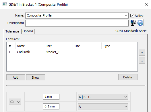
The PLTZF and FRTZF are shown below for the single face that the Composite Surface Profile GD&T was applied to. An example of 1 possible deviation is also shown:
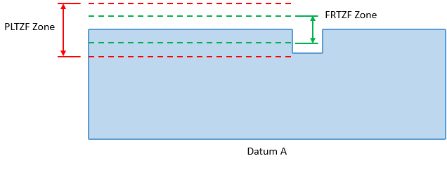
Above: PLTZF and FRTZF zones for the geometry at Nominal
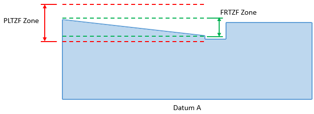
Above: PLTZF and FRTZF zones for the geometry in one possible deviation
3.One feature selected in the Features section, FRTZF is set to No DRF:
If only one feature is selected within the Features section of the GD&T dialog and the and the FRTZF DRF is set to No DRF, then the FRTZF's zone is treated as a Form refinement of the PLTZF's Location zone. An adjustment is made to the value of the amount of variation allowed for the PLTZF such that when both inputs are Normal Distributions, the two variations RSS together to form a Normal Distribution which statistically does not exceed the allowable boundary of the PLTZF.
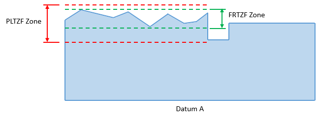
The PLTZF and FRTZF are shown below for the single face that the Composite Surface Profile GD&T was applied to. An example of 1 possible deviation is also shown:
Above: PLTZF and FRTZF zones for the geometry at Nominal
Above: PLTZF and FRTZF zones for the geometry in one possible deviation
Applying a Composite Position GD&T
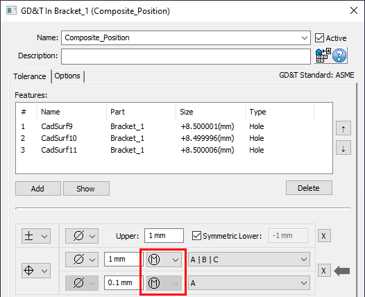
Applying a Composite Position GD&T is a bit more straightforward. Composite Position GD&T can only be applied for GD&Ts that contain two or more features in the Features section.
A Composite Position GD&T (called a Pattern callout) creates two zones (again with the top zone known as the PLTZF and lower zone known as the FRTZF) which both must be satisfied. The lower zone is a tighter zone whose location is not controlled relative to the Datums and is meant to control the location of the features relative to each other.
In 3DCS, each of the Features in the list are deviated independently of each other within the allowable range of the FRTZF then they are varied together as a Group within the allowable range of the PLTZF. An adjustment is made to the value of the amount of variation allowed for the PLTZF such that when both inputs are Normal Distributions, the two variations RSS together to form a Normal Distribution which statistically does not exceed the allowable boundary of the PLTZF.
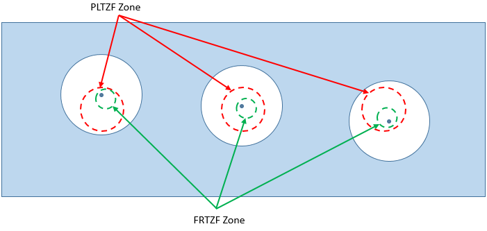
The PLTZF and FRTZF are shown below for a pattern of three holes with a Composite Position GD&T applied to it. An example of 1 possible deviation is also shown:
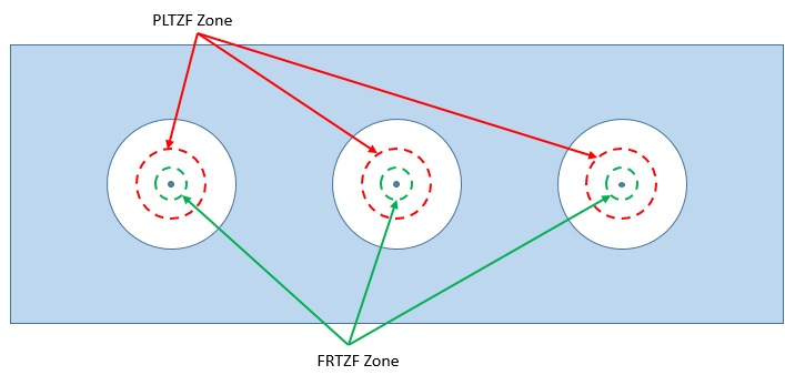
Above: PLTZF and FRTZF zones for the geometry at Nominal
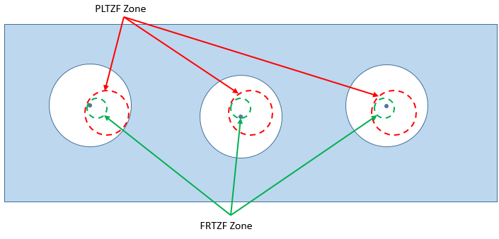
Above: PLTZF and FRTZF zones for the geometry in one possible deviation. The holes have deviated and the FRTZF zone has translated while the PLTZF has remained stationary. The center point of each hole is within the FRTZF and PLTZF.
Feature Clocking
Feature Clocking is an option that can be found in the Options tab of any Composite Position GD&T in ASME
In ISO Standard it is available for Dual Position Tolerance when the Group feature is checked.
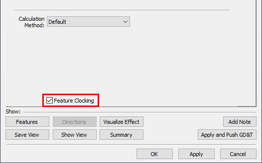
By default, the variation applied for the PLTZF only has the pattern of features translate together. There will be no rotation of the pattern of features within the PLTZF zone. Per the ASME or ISO standards, the pattern may be allowed to rotate as well as translate depending on the DRF that is used in the FRTZF. 3DCS will not automatically interpret the DRF used in the FRTZF to determine if clocking should be allowed in the PLTZF. It is recommended that if clocking is desired for the pattern of holes that the user should activate this Feature Clocking option in the Options tab of the GD&T dialog. If Feature Clocking is activated, then the allowable PLTZF zone is divided into two equal components for 3DCS to apply the variation: translations and rotation. The pattern will clock about the average center point of the features selected in the GD&T dialog. This means that when Feature Clocking is active, features closer to the average center point of the pattern will see their location deviate less within the PLTZF zone than features farther away from the average center point of the pattern.
The PLTZF and FRTZF are shown below for a pattern of three holes with a Composite Position GD&T applied to it and Feature Clocking activated. An example of 1 possible deviation is also shown:
Above: PLTZF and FRTZF zones for the geometry at Nominal
Above: PLTZF and FRTZF zones for the geometry in one possible deviation. The holes have deviated and the FRTZF zone has translated and rotated while the PLTZF has remained stationary. The center point of each hole is within the FRTZF and PLTZF.
Composite Position GD&T at MMC or LMC
When a Composite Position GD&T is created, the user has the option to add a material modifier to the callout by selecting ![]() Maximum Material Condition or
Maximum Material Condition or ![]() Least Material Condition from the drop-down. The Composite Position GD&T has a
Least Material Condition from the drop-down. The Composite Position GD&T has a ![]() Material Modifier.
Material Modifier.
While the ![]() only appears in the PLTZF line, the bonus tolerance provided by the Material Modifier has an influence on the FRTZF and PLTZF lines. Because each feature will potentially have a different size on any given build, each feature will also have a different amount of bonus tolerance allowed. Because of this, 3DCS adds the allowable bonus tolerance to the FRTZF zone such that each feature will be given a different bonus zone and then also they will vary independently of the other features. By applying the bonus tolerance at the FRTZF level, the features have also moves relative to the PLTZF DRF and so, in effect, the features have been deviated using the bonus tolerance relative to the FRTZF and the PLTZF.
only appears in the PLTZF line, the bonus tolerance provided by the Material Modifier has an influence on the FRTZF and PLTZF lines. Because each feature will potentially have a different size on any given build, each feature will also have a different amount of bonus tolerance allowed. Because of this, 3DCS adds the allowable bonus tolerance to the FRTZF zone such that each feature will be given a different bonus zone and then also they will vary independently of the other features. By applying the bonus tolerance at the FRTZF level, the features have also moves relative to the PLTZF DRF and so, in effect, the features have been deviated using the bonus tolerance relative to the FRTZF and the PLTZF.
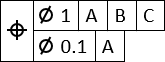
The Virtual Conditions of the PLTZF and FRTZF are shown below for a pattern of three holes with a Composite Position GD&T applied to it and ![]() selected. An example of 1 possible deviation is also shown:
selected. An example of 1 possible deviation is also shown:
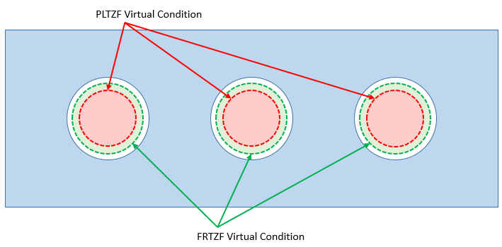
Above: PLTZF and FRTZF Virtual Conditions for the geometry at Nominal
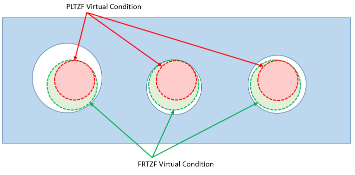
Above: PLTZF and FRTZF Virtual Conditions for the geometry in one possible deviation. The hole sizes have deviated and the hole positions have deviated about the FRTZF Virtual Condition and the PLTZF Virtual Condition has remained stationary. The Virtual Conditions of the PLTZF and FRTZF must be able to pass through the holes.
To calculate the VC in this case, you can use this simple equation:
VirtualCondition = MMC_HoleSize - MMC_PositionGD&T
In the example above:
Hole = 8.5 ± 1
PLTZF Position = 1 (M)
FRTZF Position = 0.1 (M)
So... the equation works out to be:
VC_PLTZF = (8.5 - 1) - 1 = 7.5 - 1 = 6.5
VC_FRTZF = (8.5 - 1) - 0.1 = 7.5 - 0.1 = 7.4
Remember: The FRTZF VCs can translate and rotate as long as they remain perpendicular to their DRF (Datum A). So it is larger than the VC of the PLTZF, and move around the PLTZF VCs, which are locked in space.