Construction Geometry are non-modifiable planes, surfaces, axis, and edges that will support the creation of GD&T in CATIA V5. They can be created from the Tolerance Advisor or using Construction Geometry toolbar ![]() .
.
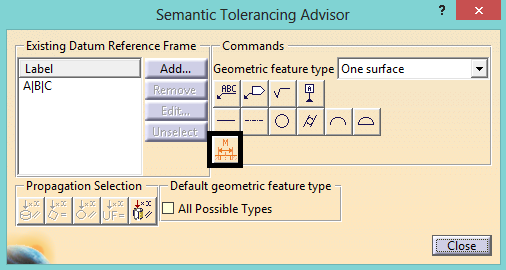
The below example shows a Thread created in Part Design and, using the Thread Creation tool ![]() , FT&A can be created to represent a Standard sized pin or hole and be used in 3DCS.
, FT&A can be created to represent a Standard sized pin or hole and be used in 3DCS.
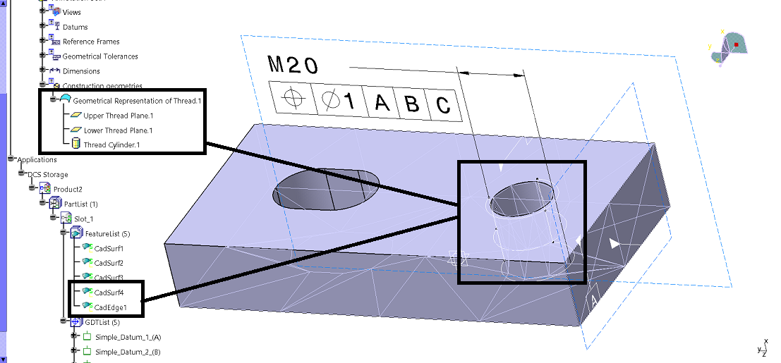
Example part:
Windows 7: C:\Users\Public\Documents\DCS\"Version"\example_models\v5_examples\GD_T\Construction Geometry
Windows XP: C:\Documents and Settings\All Users\Documents\DCS\"Version"\example_models\v5_examples\GD_T\Construction Geometry