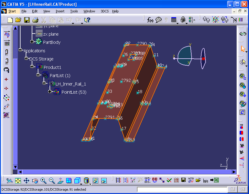
The purpose of this function is to read in the mesh nodes and their coordinates, and to create DCS points for a selected component. The points will be imported from an FEA mesh file (*.blk, *.nas, or *.inp). If the FEA mesh file has a previously defined nodes set, the function will create one DCS point at each node included in that set. If no set of nodes is defined, the function creates one DCS point at each grid node. Most FEA mesh files have a large number of nodes, therefore it is recommended to create an FEA nodes set to be imported (not every mesh node is going to be used in the 3DCS model).
|
Process
•Pick Part where the DCS modeling points will be created, from the assembly tree or graphic.
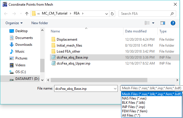
•Select the Create DCS points from FEA Mesh icon ![]() to get the Import .blk/.nas/.inp/.fem/.bdf/.cdb Files dialog box:
to get the Import .blk/.nas/.inp/.fem/.bdf/.cdb Files dialog box:

•Pick FEA mesh file, and click Open. DCS modeling points will be created.
