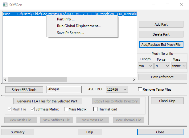
Add Part
This command allows adding a part(s) that will be treated as compliant in the model, from the tree or graph window.
Delete Part
Deletes the selected part(s) from the list.
Add/Replace Ext Mesh File
Adds the corresponding mesh file for the selected part. Pick the original mesh file created by a FEA pre-processor.
Mesh file units
The user must set these units to match the ones used in the FEA software when the mesh file was created.
In StiffGen you have to select the units for Length, Force, and Mass (when generating the mass matrix). These are the same units that were used to create the mesh file.
Available units are:
ofor Length: meter, millimeter, inch.
ofor Force: Newton, milliNewton, pound-force.
ofor Mass: kilogram, gram, pound, tonne, slinch.
▪Slinch is an English unit of mass equal to 12 slugs (386.088 pounds-mass), that accelerates by 1 inch per second squared (1 in/s²) when a force of one pound-force (lbf) is exerted on it.
ofor Thermal analysis, the mesh file must be in per unit length for each degree of Celsius temperature change.
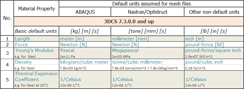
Data Reference
It is an example of typical values used in mesh files for Density and Young's Modulus.
Create 3DCS Points
This button will launch the 'Create 3DCS Points in ...(part)' dialog that can be used to add modeling (coordinate) points to the selected part by selecting mesh nodes from the original mesh file. This application uses the original mesh file and it needs the Length, Force, and Mass units that were used to generate the mesh file. No Nominal Build or point/node linking is required.
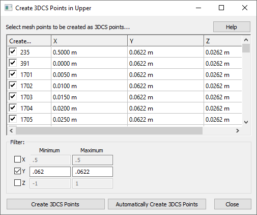
Users can create points the following ways:
1. Activate the Filters X, Y, or Z (or a combination) and set the Minimum and Maximum values (press the Enter key to update values). These values will retain all the nodes with coordinates within the specified interval. The list can be further modified, by changing the limits or deselecting the points manually. Click the Create 3DCS Points button to create the selected points in the list. The created points will show up as coordinate points with the following name: DcsPtFromMesh235, where '235' is the mesh node label.
2. Create one point for each node, since all nodes are initially selected in the dialog. This may create a very large number of points, most of then unnecessary. It would also slow down the model, therefore this option is not recommended.
3. Automatically Create 3DCS Points - this option is still under construction.
Notes:
oTo deselect the entire list: Select all (click in the first cell and then Ctrl+A), then deselect all.
oThe points will be created at the correct location even if the selected nodes are shown at the location where the mesh was created, in most case - design position.
Precheck Linking Distance
Can be used to validate the distance from each modeling point to the closest mesh node, prior to linking them to each other. Sometimes a user might have extra, or missing points in the model, or points that will not align well to any FEA mesh node location. This function can show the user how far the DCS points are from the FEA nodes and thus help make mistakes evident.
▪This application requires a part (Add Part), the original mesh file (Add/Replace Ext Mesh File), and the 'Mesh file units' to be selected (Length).
▪In the Precheck Linking Distance dialog, the Enter key updates the list of points to show only the points whose distance from the closest mesh node is larger or equal to the set value.
▪The units used in the Precheck Linking Distance dialog are consistent to the units selected for Length in the StiffGen dialog.
Select FEA Tools
1.Executable file (*.EXE file)
This command allows the user to select the FE Solver installed on your computer that will be used to generate the FEA files. A different solver can be selected for each part, to generate the matrix files based on the mesh type. The solver will be an executable file such as abq6141.exe, or Nastran.exe.
2.Batch file (*.bat file)
This command allows the user to select a batch file which can be used to call the FE Solver installed on the server. An initial batch file is needed with the information about the FEA solver on the server. This batch file will then be edited and used to submit the mesh files over the server.
ASET DOF
Allows selecting between 3DOF (123 - translations only) and 6DOF (123456 - translations and rotations) for creation of stiffness, mass and load matrices. These options are available for shell mesh only. The solid mesh will always generate a 3DOF matrix.
Remove Temp Files
This check-box is inactive by default.
When FEA matrices are generated a set of files that accompany the mesh, stiffness, mass, and thermal files are also created. By checking this box these extra files will be automatically removed at the end of the process. The purpose is to free up computer space since some of these files can be quite large.
Generate FEA Files for the selected part
Mesh File - is updated with the set of nodes that are linked to modeling points. Commands are added to the Mesh file to create the Matrix files. No other changes are made to the original mesh file.
Stiffness Matrix - when checked is going to create a reduced stiffness matrix for the set of nodes that were added to the mesh file.
Mass Matrix - when checked will create a mass matrix (used in the Gravity move) for the set of nodes that were added to the mesh file.
Thermal Load - when checked will generate the Thermal Load file for the part or points listed in the Thermal Move. You need a thermal move created in the model before you can create a Thermal Load file in StiffGen.
Create Load FEA Data move: With this option and after completing the Stiffgen dialog, a Load FEA move will be created after select OK with the correct FEA and Mesh files linked to the parts. This setting is defaulted OFF, so that it does not create unwanted moves.
Copy Files to Model Directory: This command copies the Mesh and Matrix files from the default directory where they are created to the model directory. If more than one part is selected, all parts will be copied to the model directory.
View Mesh File, View Stiffness File, View Mass File, View Thermal File: This command will open the generated file in a Notepad or WordPad format for viewing. The mesh file will be updated with ASETs.
Global Disp (or RH-menu Run Global Displacement...)
This function creates a displacement file(*.dat) which includes the value of displacement for each mesh node (translations and rotations). The displacement is based on the nominal or any other build position of the part. The *.dat file can be created for each compliant part. You would need a Mesh file to use this feature. The output file is also created; this file can be opened in Abaqus and deformation can be measured and visualized.
This option is only available for the Abaqus solver at this time.
Other RH-menu functions:
Part Info... provides information for the selected part including local and global coordinate system, loaded mesh file, part's MTMs and also what MTMs are using the part.
Save Pt screen... creates a file that saves the screen coordinates for all points in the part.
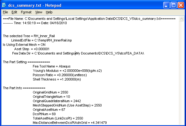
Summary: The Stiffness Matrix and FEA Mesh parameters with their calculated values are listed in the Summary file.
Help: The Help button is context sensitive; it will open the Help Manual at required topic page.
Close: This command will close the Stiffness Generating Dialog box.
|