Create a GD&T Measure for the position of the Stick top spherical surface. This measure will calculate the Position Tolerance value that can be met by the simulated assembly.
•Click the ![]() Measures button from the Model Creation toolbar and select the top assembly from the tree.
Measures button from the Model Creation toolbar and select the top assembly from the tree.
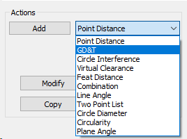
•Select GD&T from the drop down and click [Add].
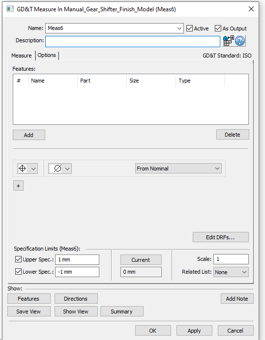
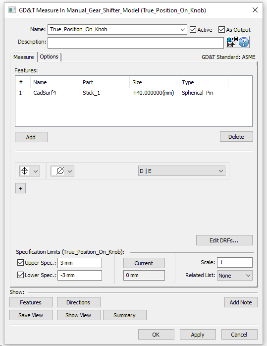
•Change the Name to "True Position Of Knob".
•Click [Add] and select the Knob surface from Stick.
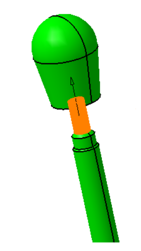
•Make sure the ![]() Diameter symbol is selected.
Diameter symbol is selected.
Now we have to link the Measure to the Datum Reference Frame.
•Select [Edit DRFs..]
•Under Datum Features click on Datum D, then Datum E. As you do this D and E will appear in the Add/Modify DRF boxes.
•Select [Add] and the Datum Reference Frames window will display D l E .
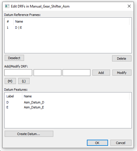
•Click [OK] to return to the GD&T Measure dialog.
•Make sure the True Position [picture] symbol is selected.
•Make sure the ![]() Diameter symbol is selected.
Diameter symbol is selected.
•Select D l E from the drop-down list.
•Set the limits as +3mm/-3mm.
The completed Measure should look like the image below. Now the measure will check the diametral position variation of the knob relative to the DRF defined by the feature datums D and E. Please note this measure is calculating the output variation of the model. Later on you will use GD&T callouts to define the input variation for each part.
•Click on [Ok] to create the measure.
Measure Reorder
Reorder the "True Position on Knob measure" to be the 3rd Measure so it comes right after the "Shifter Knob X Dir" Measure.
• From the Measure List Dialog select the measure "True Position on Knob"
• Click the drop down from "Switch To" Tab and select #3 from the List
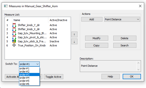
This will move the measure to the 3rd position in the List.
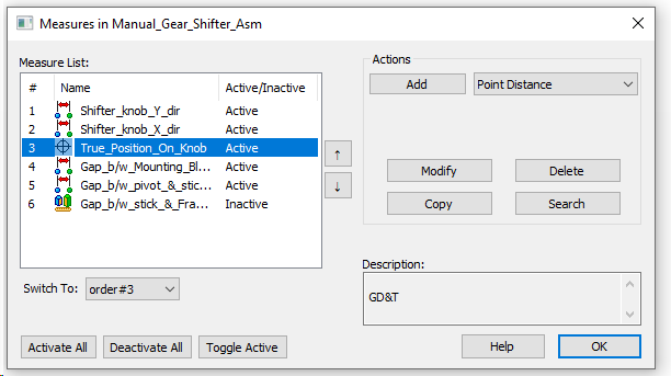
•Click OK to close the measure list dialog and Save the Model