First, save the model under a new name to start the lesson.
•With the Analyst_Tutorial_Lesson5 tab open, Go to the North quadrant of the Compass (called My Social and Collaborative Apps) and select the Collaborative Lifecycle app.
•Select the Analyst_Tutorial_Lesson5 Simulation and select ![]() Duplicate from the toolbar at the bottom.
Duplicate from the toolbar at the bottom.
•Right-click on the new duplicated Analyst_Tutorial_Lesson5 Simulation in the model tree and select Properties.
•In the Reference tab of the Properties dialog, change the Title to "Analyst_Tutorial_Lesson6".
•In the Compass, go to the South Quadrant (called My Content and Simulation Apps) and select 3DCS Variation Analyst V6 in the V+R My Simulation Apps section to return to the 3DCS Variation Analyst workbench.
•Go to File ![]() Save Management.
Save Management.
•Select the Lesson5.CATProduct and select [Save As...].
•In the Save As dialog, rename the Product to "Lesson6.CATProduct" and click [Save].
•In the Save Management dialog select [OK] to save the CATIA Product under its new name. The model is not saved until you click OK.
•Click the ![]() Application Button then select
Application Button then select ![]() Save As.
Save As.
•Change the File Name to "Lesson6.wtx".
•Click [Save] in the Save As dialog.
•Go to File ![]() Save As.
Save As.
•In the Save a Copy dialog, enter "Lamp_SubAsm_Lesson6" for the File Name, make sure the Type is set to Assembly (*.asm), then click [OK].
•In the Assembly Save a Copy dialog, click [Save Copy and Open] to save the assembly under its new name, and open the newly saved assembly.
•Close the 3DCS Model Navigator and Creo window for Lamp_SubAsm_Lesson5.
•Click ![]() Update Model in the new window for Lamp_SubAsm_Lesson6.
Update Model in the new window for Lamp_SubAsm_Lesson6.
•Go to File ![]() Save As.
Save As.
•In the Save As dialog, enter "Lamp_SubAsm_Lesson6" as the new File name and make sure the type is set to Part Files (*.prt).
•Click [OK] in the Save As dialog.
•Click ![]() Update Model.
Update Model.
•Go to File ![]() Save As.
Save As.
•In the Save as dialog, enter "Lamp_SubAsm_Lesson6" for the File Name, make sure the Type is set to Assembly.
•Click [Save] in the Save As dialog.
•Click ![]() Update Model.
Update Model.
First, we will create the measure at the top of the gap. Similar to the moves, the parent of the measure will be Lamp_SubAsmLamp_SubAsm_Lesson6 to include all the variation at the part level and any variation from the floating.
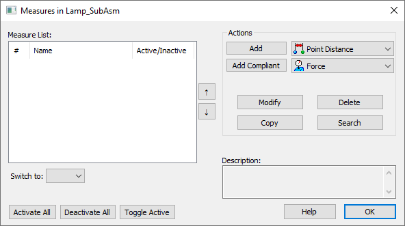
•Click the ![]() Measures button then select the Lamp_SubAsmLamp_SubAsm_Lesson6 from the tree. This will open the Measures dialog.
Measures button then select the Lamp_SubAsmLamp_SubAsm_Lesson6 from the tree. This will open the Measures dialog.

•Select Point Distance as the measure type from the drop-down list next to [Add].
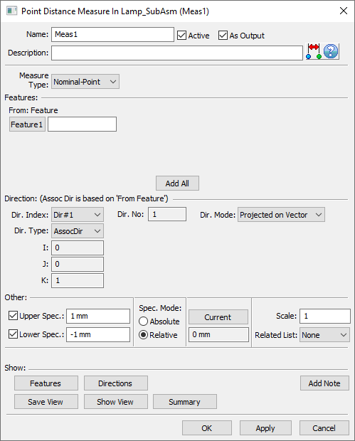
•Click [Add]. This will open the Point Distance Measure dialog.

•Change the Name to "Upr_Gap".
•Add a Description of "Upper gap variation between Turnlamp and Headlamp."
•Change the Measure Type to Point-Point and the To: Feature field will be added to the dialog.
•Click [Add All].
•Select the point TurnLp_Upr_Gap in the Turnlamp.
•Select the point HeadLp_Upr_Gap in the Headlamp.
After selecting the second point, the Point Distance Measure dialog will reopen. The Direction section of the dialog sets exactly what distance between the two points will be measured. With Projected on Vector selected for the Dir. Mode, the direction being set is the direction along which the distance will be measured. When the direction is set to AssocDir the direction 3DCS uses is the direction of point selected in the From: Feature field (the first point). It is possible to set a different direction or change the Dir. Mode to Projected on Plane or True Distance for different ways of measuring the distance between the two points. The help manual contains much more information about directions and the Point Distance Measure.
•In the Direction area of the dialog, set the Dir. Mode to Projected on Vector.
•Set the Dir. Type as AssocDir.
•In the Other area, set the Upper Spec as 1.5mm and set the Lower Spec as -1.5 mm.
•Set the Spec. Mode to Relative.
•Click [Apply] to save the measure.
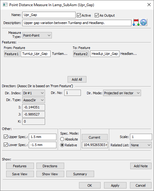
The completed Upr_Gap measure should look like the image below. Your current measure value will be different depending on how far you separated the Headlamp and Turnlamp.

•Click the [Features] button to show the features used in the measure.
•Click [Close].
•Click the [Direction] button to show an arrow pointing in the measured direction.
•Click [Close].
•![]() Nominal Build then click the [Current] button. The measure value will update to the nominal value.
Nominal Build then click the [Current] button. The measure value will update to the nominal value.
•Click ![]() Separate.
Separate.
•Click [OK] to close the Point Distance Measure dialog.