Geometric Tolerance
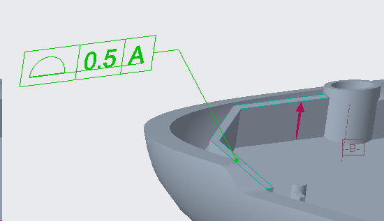
Select the Geometric Tolerance![]() icon from the Tolerance section and pick the surface.
icon from the Tolerance section and pick the surface.
This will create a Geometric Tolerance frame with the default types in it.
Middle mouse click in the Graphics to place the Frame.
Now the user can go ahead and do further editing for the created GTOL.

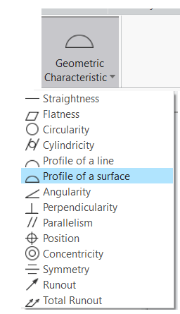
Geometric Characteristic
The GD&T Type can be selected under the Geometric Characteristic drop down menu.

Tolerance and DRFs
The Tolerance value and the DRFs can be selected from the Tolerance and Datums section. It is a good idea to name the tolerance because this is what 3DCS will extract.
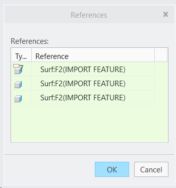
References
Additional references can also be added from the Reference dialog

Composite Frame
The Composite Frame command displays the sliding panel that enables you to define the composite GTOL symbol.
The sliding panel provides you with the Composite Frame table enabling you to define the tolerance value and datum reference compartments belonging to the composite frame. The frame table provides you with four following columns: Tolerance, Primary, Secondary and Tertiary.

