Extracting Creo GD&T into 3DCS:
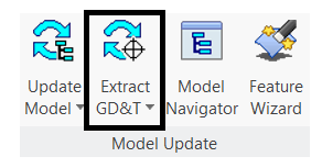
•Switch to the 3DCS work bench and press Update Model to load the model into 3DCS and to see the 3DCS Navigation Tree.
•Next to Update Model, select Extract GD&T. For best results when importing PMI into 3DCS, users should define the PMI on surfaces.
•This will open an Extract GD&T selection dialog prompting the user to select the component to extract the GD&T from. The user can either select an individual component or the root to extract the GD&T from all parts in the model.
•Selection can be done either from the Creo Navigation Tree or the 3DCS Navigation Tree and the Creo Graphics Window.
The extracted GD&T will be displayed in the 3DCS Navigation Tree within each part.
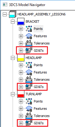
The extracted GD&T will have unique tree icon to differentiate from the 3DCS created GD&T.![]()
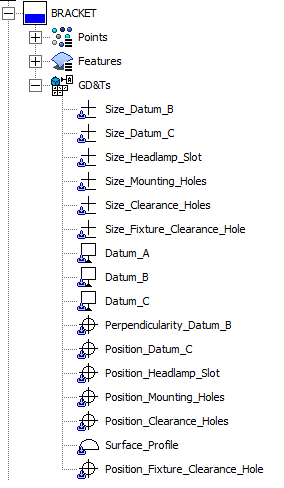
•The name entered in Creo is extracted with the GD&T and is the displayed name in 3DCS.
•In 3DCS, the GD&T dialog for each part lists all extracted GD&T.
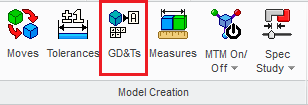
Double-click GD&T under a part/subassembly in the 3DCS Navigation Tree or select GD&Ts from the Model Creation toolbar and select a part/subassembly to open the GD&T dialog for that part/subassembly.
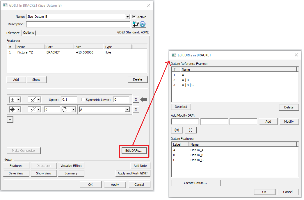
•The GD&T List dialog lists all the GD&Ts for the selected Part.
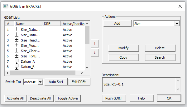
•Double Click a GD&T from the list to open the GD&T Dialog.
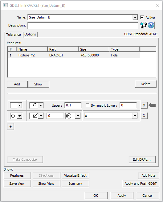
•Notice the selected GD&T opens and also if the same feature is used in another GD&T callout, the dialog combines it as well.
•The Features extracted will be listed under the Features section.
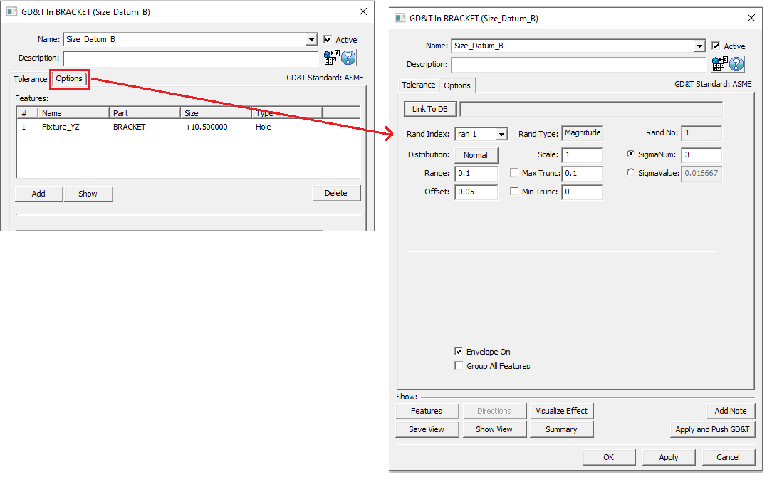
•Select the Options Tab for further information on the GD&T.
•All the options can be edited.
•Select “Edit DRFs” to open the Edit DRFs Dialog which lists all the Datum Features and DRFs extracted from Creo.
•Users can still create New Datums and also create new DRFs by using the extracted Datums.