Here is a list of best practices to create GD&T needed to extract into 3DCS.
|
Activate Annotation Display
•If the GD&T created is not shown in the Graphics Window, make sure Annotation Display is turned on in the Quick Access toolbar.

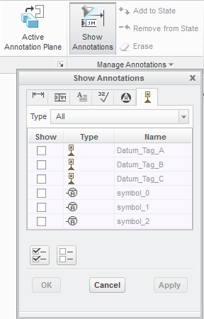
•If the GD&T created in the Part level should be displayed in the assembly level Graphics Window, go to the Annotate tab, select Show Annotations, and select a part from the assembly in either the Creo Navigation Tree or Graphics Window. The Show Annotations dialog will list all GD&T created within the selected part from which the user can hide/show any GD&T.
Note: Be sure to check the Dimensions, GTOLs, and Datum Tags tabs to hide or show all desired GD&T |
|
•When the Datum Tag is attached to the GTOL frame, the Datum Tag follows the GTOL automatically when repositioned, preserving the attachment point on the GTOL frame.
•To edit the created GD&T in Creo the user should be in the Annotate workbench.
•To replace an annotation reference, right-click its name in the References collector, and click Replace on the shortcut menu, and select a new reference entity of a similar type.
Note:The user cannot replace references that are added using the Surfaces collector after the annotation is created in the Annotation Feature dialog. The user must remove the unwanted references and add new references.
•The Surfaces collector in the Annotation Feature dialog’s Surfaces section lets you select additional surfaces to be associated with the active GD&T. The Details... button below to the Surfaces collector opens the Surface Sets dialog box, which provides you with a variety of tools for defining surface sets.
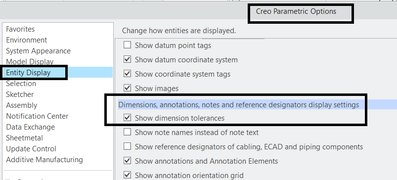
Options: While trying to add tolerance to the dimensions and if that option is not available, turn on the setting in Creo options.

