The
Some of the more common feature control frames that can be represented by dual tolerance are:
Example Model:C:\Users\Public\Documents\DCS\3DCS_V5_8_2_0_0\3DCS CAD & Example Models\Reference Models\Tolerances\Dual Tolerance
|
Input Required:
•2 Distributions
•2 Magnitudes
•Tolerance Name
•2 Directions
•Point List
•Description (Optional)
Methodology:
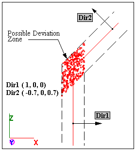
The tolerance acts along two linear directions within the two specified ranges. The directions are specified by two different vectors, which do not have to be mutually perpendicular.
1.The magnitudes by which the point is to be deviated linearly are calculated from the range and offset (or plus and minus), distribution, type, sigma, truncation and scale values.
2.The point associated with the tolerance is deviated along the specified vector directions within the defined tolerance range.
Parameters Specific to Dual Surface Tolerance:
•Mode has been outlined below as a specific parameter.
•Click on Add Indiv. next to the points list, to graphically pick the points to which the tolerance should be applied. Multiple points may be selected at one time by clicking the Add Win. button and dragging a window around the desired points. The points can also be picked by keying in the name of the point in the Key In field. The points can also be picked by keying in the name of the point.
•Click Rand drop-down list (# 1 & 2), to define the ranges (plus & minus) for the points.
•Click Dir#1 & Dir#2 to define the direction vectors for the points.
•The Dir# and the Rand# are linked together in the menu (Ex: by selecting Rand#1, Dir#1 will be automatically selected).
•When all the points are picked, click on OK and the tolerance is defined.
Mode:
Mode only applies when more than one point is being toleranced.
Specifies the mode option for the tolerance.
The mode field lets you specify different combinations of magnitude and direction for greater flexibility. The mode option has two choices: Individual and Group Mode.
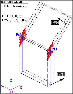
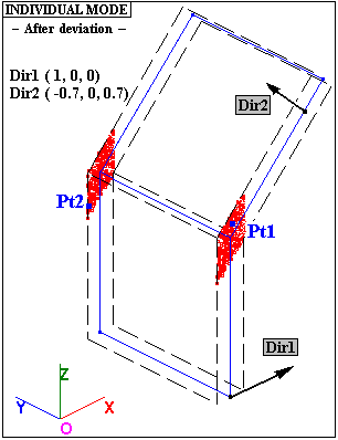
Individual:
When Individual Mode is specified, each point in the list that is associated with the tolerance, varies with two independent magnitudes in the specified ranges, along the two vectors.
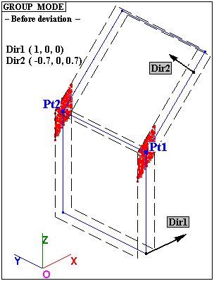
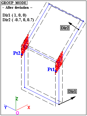
Group:
When Group Mode is specified, each point in the point list box that is associated with the tolerance, varies with the same two magnitudes in the specified ranges along the same two vectors.
Note:When creating the Dual and Triple tolerance, the tolerance and measurement directions must match.
|