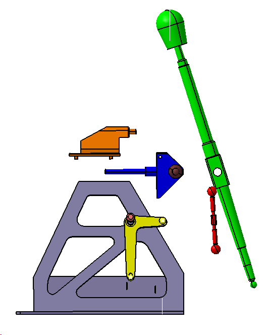
It's good practice for parts to be translated away from each other to verify all moves have been created correctly. This also makes it easier to view the assembly process.
First we will create some points to be used later.
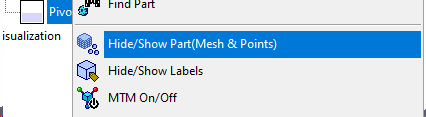
•Hide the Pivot and Select Pin Part by selecting both parts in the tree and selecting "Hide/Show Parts(Mesh&Points)" from the tree right click menu.
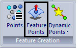
•Select Feature Points under Feature Creation Toolbar to open the Feature Point dialog.
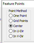
•Select "Center" under Point Method.
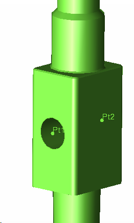
•Click Select Feature and select the hole feature in the Stick. Select the inner surface, not the ends.
•Click Create Points. A point should appear at one end of the hole.
•Now change the v[0-1] value to 1 and again click Create Points
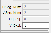
•Another point should appear at the other end of the hole.
•Close the Feature Points dialog.
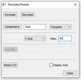
•Under the Geometry tab, select ![]() Translate/Rotate function and select Component.
Translate/Rotate function and select Component.
•In the Translate/Rotation dialog, select [Component] and then select the stick part.
•Make sure the mode is on Translate and the direction is on the X-Axis direction.
•Change the Step number to 60mm and hit [Increase].
•Click the drop down button next to Translate and select Rotate.
•Click the drop down next to x axis and select line.
•Click Line Pts from the dialog and select the 2 points created in the center of the Stick hole.
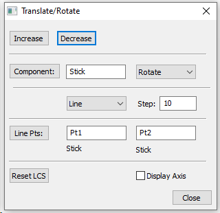
•Change the Step number to 10 and select [Decrease]. Rotating a part more than 15° from its built orientation is not recommended
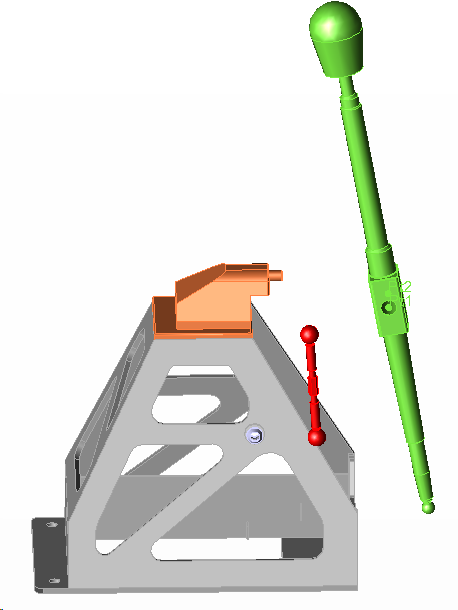
•Similarly Translate all other parts different distances (Rotate is not necessary for other parts).
•Delete the Points created on the Stick and unhide the Pivot and Select Pin Parts.
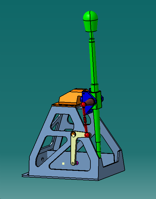
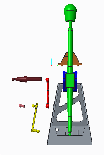
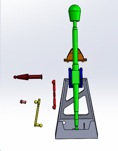
•The assembly should look like the following image.
.
Creating Scenes
A set of scenes will allow you to switch between several positions of specified parts, sub-assemblies, or for the entire assembly. For example, the parts can be exploded or reset to their original design position using a saved scene. Any assembly stage can be saved as a scene. This can also be used to maintain other settings such as part color, transparencies, or hidden parts.
•Make sure you are in ![]() Creation Mode.
Creation Mode.
•Go to the Start menu and select Mechanical Design ![]() Assembly Design.
Assembly Design.
•Find the Scenes toolbar.

•With the parts in the initial (nominal) position, click the ![]() Enhanced Scene button to open the Enhanced Scene dialog box.
Enhanced Scene button to open the Enhanced Scene dialog box.
•Select [Full] for Overload Mode
•Uncheck the Automatic naming option then enter "Design" into the Name field.
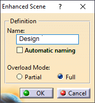
•Click [OK].
The screen background changes to green every time a scene is activated. A warning message may appear about performing moves that may invalidate analysis results. This message may appear every time the user enters a scene.
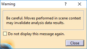
•[Close] the warning.
•Click the ![]() Exit Scene icon shown below in the Enhanced Scenes toolbar to save the current position of the parts and return to the model.
Exit Scene icon shown below in the Enhanced Scenes toolbar to save the current position of the parts and return to the model.
Translate Parts
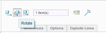
•Drag the Compass to the Stick by clicking and holding on the squarecircle at the base of the compass.
•In the Navigation Tree, highlight the Stick (the Compass should turn greenorange).
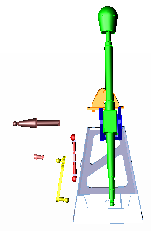
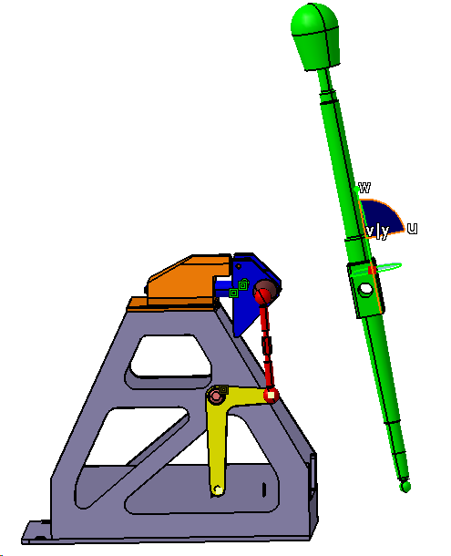
•Select the Compass on the line in the U/X direction, drag the two parts about 80 mm away from the Frame along X direction (as shown in the image below).
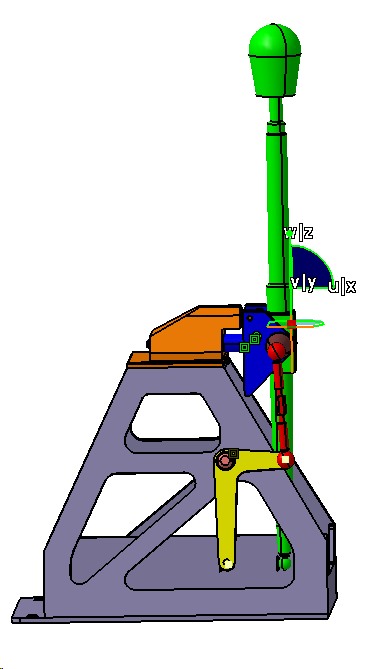
•Now Rotate the stick slightly toward the Frame for about 10degree
•Now repeat the same process to separate all the Parts from each other.
•The Translated parts should be similar to the image below.
Front View
Left View
•Return the compass to the corner.
•Click Update Model
For further information on this function, please go to Manipulation, or see the CATIA Online Documentation page entitled "Moving Objects Using the 3D Compass".
Note: The Catia's Translation or Rotation command may also be used to translate and rotate parts or sub-assemblies. This command will translate and rotate components by a specified increment.
Creating a Separated Scene
Similar to creating the Nominal Scene, you can create another scene for Separated position.
•Find the Scenes toolbar again.
•With the parts in the separated position, click the ![]() Enhanced Scene button to open the Enhanced Scene dialog box.
Enhanced Scene button to open the Enhanced Scene dialog box.
•Select [Full] for Overload Mode
•Un-check the Automatic naming option then enter "Separated" into the Name field.
•Click [OK].
The screen background changes to green every time a scene is activated. A warning message may appear about performing moves that may invalidate analysis results. This message may appear every time the user enters a scene.
•[Close] the warning.
•Click the ![]() Exit Scene icon shown below in the Enhanced Scenes toolbar to save the current position of the parts and return to the model..
Exit Scene icon shown below in the Enhanced Scenes toolbar to save the current position of the parts and return to the model..
•Switch to the Model tab and click ![]() Manage Views.
Manage Views.
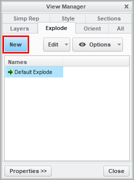
•In the View Manager dialog, select the Explode tab and click [New].
•Type "Exploded" as the name and press the Enter key to create the Exploded View.
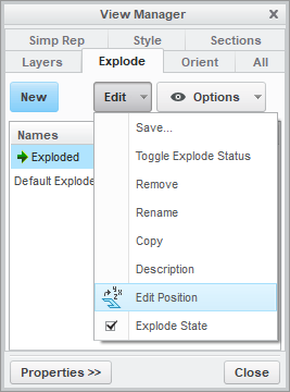
•With Exploded highlighted, click [Edit] then select Edit Position.
•In the Creo Model Tree, select the Frame. A compass will appear on the screen.
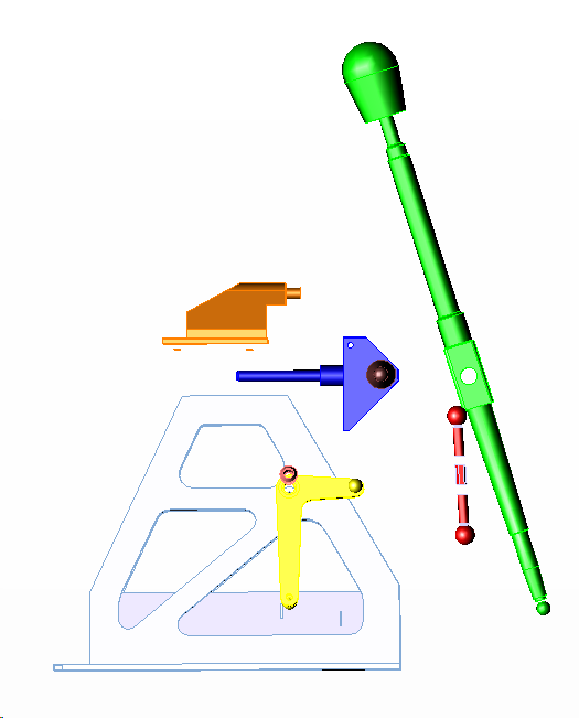
•Drag the arrow of the compass to move Frame about 60 mm in the X-direction away from the Base (as shown in the image below).
•Now select the Rotate option and select the side surface of the stick to tilt the stick for 10 degrees.
•Only the Stick part need to be rotated.
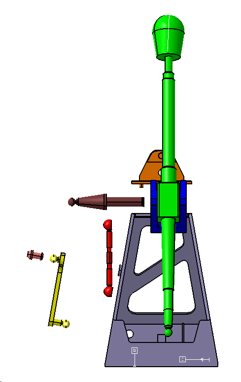
•Translate the other parts referring the images below.
•Click the Green Check Mark in the Explode Tool tab.
•Click [Edit] then select Save... .
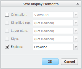
•In the Save Display Elements dialog, make sure Explode is checked and Exploded is selected from the drop-down list, then click [OK].
Exploded should no longer have a "(+)" next to it and should have a green arrow to the left of it. This indicates that it is the current active Explode State.
•Click [Close] in the View Manager dialog.
In the Model tab, when the [Exploded View] button is active, the parts will be in their exploded positions. When the [Exploded View] button is inactive, the parts will return to their as assembled positions. You need to ![]() Update Model after you activate or deactivate the [Exploded View] button so that the 3DCS data stays with the Creo parts. This can be seen after adding points or features to the model.
Update Model after you activate or deactivate the [Exploded View] button so that the 3DCS data stays with the Creo parts. This can be seen after adding points or features to the model.
A set of arrangements will allow the user to switch between several positions for specified parts, sub-assemblies, or for the entire assembly. For example, the parts can be exploded or reset to their original design position using saved arrangements. Any assembly stage can be saved as a arrangement. All parts must be set to 'Individually Positioned' for the arrangements to function correctly.
•Select all parts. Do this by one of the following methods:
1.In the graphics area, drag a box around all three parts.
2.In the Assembly Navigator, click the first part in list then shift+click the last part in the list.
•With all parts selected, right-click and select Properties.
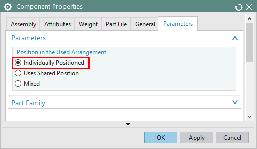
•In the Parameters tab, in the Parameters section, under Position in the Used Arrangement, select Individually Positioned.
•Click [OK] to close the Component Properties dialog.
•In the Assembly Navigator, right-click Lesson_3 Manual Gear Shifter Asm and select Arrangements ![]() Edit...
Edit...
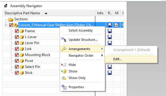
•Select Arrangement 1 (Default) and click ![]() Rename. Rename the arrangement "Design".
Rename. Rename the arrangement "Design".
•Click ![]() New Arrangement and name it "Exploded".
New Arrangement and name it "Exploded".
•With the Exploded arrangement still selected, click ![]() Use. The completed Assembly Arrangements dialog should look like the image below.
Use. The completed Assembly Arrangements dialog should look like the image below.
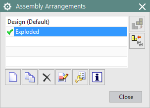
This will set the Exploded arrangement as the active arrangement. Next, when we separate the parts, the Exploded arrangement will be used to save the exploded position of the parts. The Design arrangement will be used to save the design position of the parts. The arrangements can be used to quickly switch the part positions between design and exploded.
•Click [Close] in the Assembly Arrangements dialog
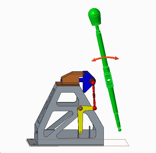
•Select Stick, right-click and select the ![]() Move icon.
Move icon.
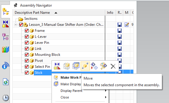
•In the Transform section, select Dynamic for the Motion type.
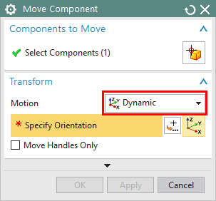
•Drag the XC arrow of the trihedron to translate 60 mm in the x-direction.
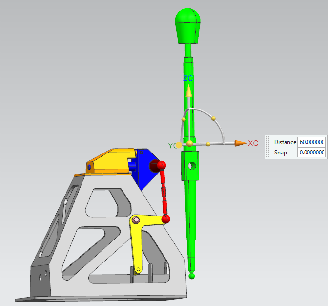
•Also rotate the part about -10 degree along YC axis.
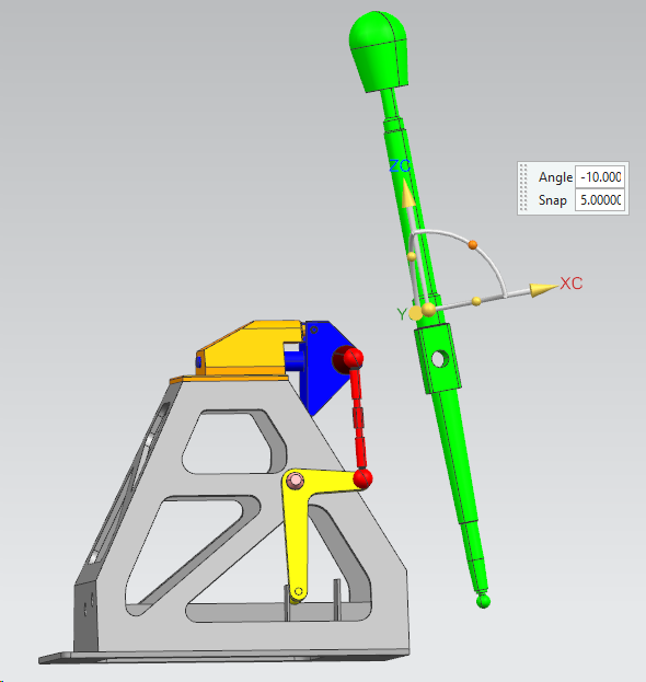
•Click [<Apply>] in the Move Component dialog.
•Now Move the other parts, no rotation is required for other Parts.
•The Parts after Translation should like the image below.
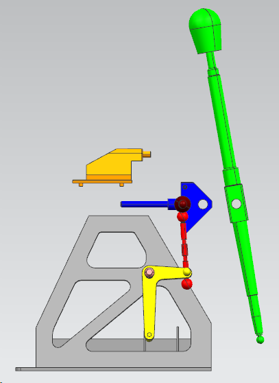
Front View
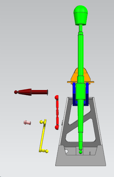
Right View
•If needed, click ![]() Fit to display all parts on screen.
Fit to display all parts on screen.
•To use the arrangements, right-click Lesson_3 Manual Gear Shifter Asm in the Assembly Navigator then select Arrangements ![]() Design. The parts will move back to their design position.
Design. The parts will move back to their design position.
•Right-click Lesson_3 Manual Gear Shifter Asm in the Assembly Navigator then select Arrangements ![]() Exploded to return the parts to their exploded position.
Exploded to return the parts to their exploded position.
•Click ![]() Update Model
Update Model
We must ![]() Update Model because translating the parts and using arrangements are NX functions that do not take effect in 3DCS until the model is updated. This will become evident after we create features in 3DCS.
Update Model because translating the parts and using arrangements are NX functions that do not take effect in 3DCS until the model is updated. This will become evident after we create features in 3DCS.
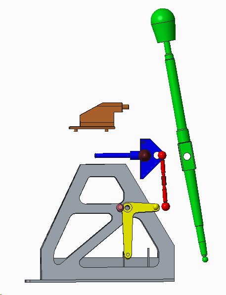
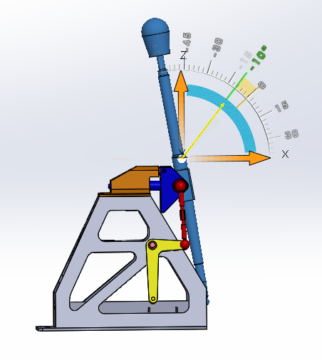
•Right click the Stick from the tree and select Move with triad option.
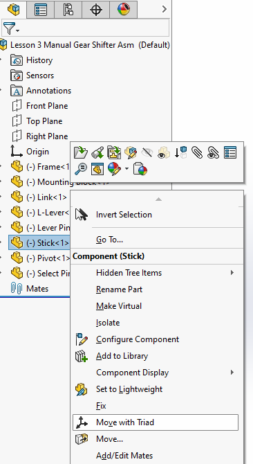
•Rotate the Stick -10 degrees along the ZX axis like shown below.
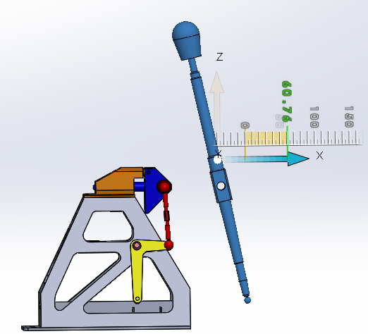
•Again select the Stick and Translate the part 60mm along X axis.
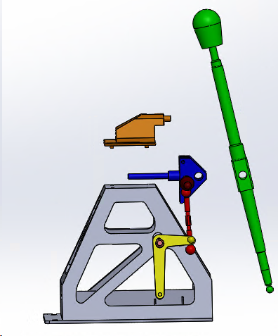
•Similarly select other parts and move away from each other following the same steps.
Refer the image below to translate the parts
• In your Apps and Roles quadrant, select "Assembly Design".
•Drag the Compass to each part and try to separate the parts as shown in the image below.
• Save the Model