The purpose of the
|
Inputs
Select the Compliant DefoMorphing Move icon ![]() to get the DefoMorphing Move dialog box:
to get the DefoMorphing Move dialog box:
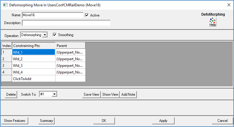
•Name: The move name must be unique to the model.
•Description: This is an optional explanation of what the move does.
•Help: The Help button is context sensitive; it will open the Help Manual at required topic page.
•Operation: Allows the user to select the appropriate operation for the move. The drop-down list lists: Clamp, UnClamp, Weld, LockDOF, UnLockDOF, Contact, Un-contact and DefoMorphing..
•Check the box to Turn On Smoothing
•Constraining Pts: These are the points that will be constrained. The number of points can be from 1 to n.
Outputs
•The result of this routine will be the deformed part due to the constraining points location and variation.
Process
•Select the DefoMorphing Move Icon ![]() and choose the location for the DefoMorphing Move. This move must be at a product level, at least one level above the part.
and choose the location for the DefoMorphing Move. This move must be at a product level, at least one level above the part.
•Use ClickToAdd to add or remove Fixed points.
•Use the Switch To drop-down to reorder the points.
•Use the Show: Features button to display the points on the screen.