The purpose of the
|
Inputs
You only need the Input Deck (*.nas, *.blk, or *.inp) and the Output File (*.out, *.dat, or *.f06).
Note: A Load FEA routine is needed to load the mesh file. The stiffness matrix file is not required for this routine, so a dummy file (*.bdf, *.pch, or *.mtx) can be loaded in the Load FEA routine.
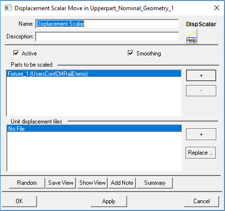
Select the Displacement Scalar move icon ![]() to get the Displacement Scalar Move dialog box:
to get the Displacement Scalar Move dialog box:


•Name: The move name must be unique in the model.
•Description: This is an optional explanation of what the move does.
•Help: The Help button is context sensitive; it will open the Help Manual at required topic page.
•Check the box to Turn On Smoothing
•Parts to be scaled: The number of parts can be 1 or more.
•Unit displacement files: The drive and directory where the output file is located.
Notes:
•The number of parts and output files must be the same.
•The first part will be linked to the first output file, the second part with the second output file, etc.
•The output file will have a *.out, or a *.dat extension, depending on the software used to create the stiffness matrix file.
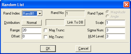
Random
•Distribution: See Distributions
•Range: is the ±3Sigma value used to produce a randomized Scalar value (see below). The Scale is applied to all modeling points linked to ASET nodes.
The Displacement Scalar method applies the following equation:
[P] = [Po] + Scalar * [d]u, where
[P] is the resultant XYZ vector for all meshed points at deformed position
[Po] is an XYZ vector for all meshed points at nominal position
Scalar (Range) is a random value.
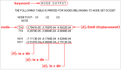
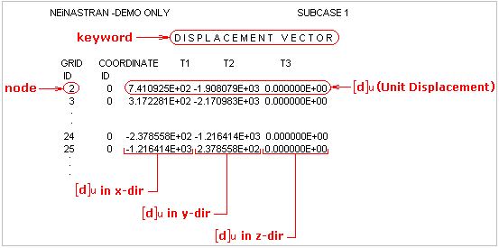
[d]u is a Unit Displacement vector. Given a case of fabrication deformation, a unit displacement vector [d]u is read from an Output File.
Examples of displacement vectors:
a) For files generated using Abaqus solver (*.dat) the keyword used is: N O D E O U T P U T:

b) For files generated using Nastran solver (*.out) the keyword used is: D I S P L A C E M E N T V E C T O R:

•Max Trunc: The value by which the maximum displacement value will be truncated (cut off at a certain point). This option is only active when a check mark is present next to the field.
•Min Trunc: This option is only active when a check mark is present next to the field. Min Truncation means to cut the displacement at a particular low end point.
•Offset: If the offset is not zero, the displacement range is not split equally. For example, if the range is 6 and offset is 1 then the displacement will be from -2 to +4. If the offset equals zero the displacement is from -3 to +3.
•Sigma #: This value relates the range to the number of standard deviations the range includes. Half the range is divided by this number to determine the standard deviation of the displacement. The Sigma Num is a number greater than 1.0 with up to four decimal places. The default value is 3.0. This specification is required for the Normal, Weibull, Step, Left Skew, and Right Skew distributions.
•HLM Level: HLM or High-Low-Mean level specifies the number of "in between" levels that a displacement is varied within its range. The HLM level is specified by a number between 2 and 8. A higher degree of accuracy is achieved as the HLM number gets bigger. However a bigger HLM number slows down the simulation. By default the HLM level is specified at 3. The HLM number specified, affects the Sensitivity analysis only.
•Summary: The part names with their output files are listed in the Summary file.
Outputs
The result of this routine will be the deformed part based on the Range value.
Process
•Select the Compliant Displacement Scalar Move icon ![]() and choose the location for the Displacement Scalar Move. This move must be at a product level at least one level above the part. The Displacement Scalar dialog box will appear.
and choose the location for the Displacement Scalar Move. This move must be at a product level at least one level above the part. The Displacement Scalar dialog box will appear.
•Select the Parts with Displacement plus ![]() button to begin loading the parts. Multiple parts can be loaded at the same time. When finished click Close in the Pick Part dialog box to return to previous dialog. After loading all the parts, click on the plus
button to begin loading the parts. Multiple parts can be loaded at the same time. When finished click Close in the Pick Part dialog box to return to previous dialog. After loading all the parts, click on the plus ![]() sign in the Displacement File Path window. The output files will be loaded for each part, one at a time, until all parts have one output file each. Clicking the Cancel button can interrupt this process. If the wrong output file was loaded, the user can replace it by selecting the file and clicking the Replace button.
sign in the Displacement File Path window. The output files will be loaded for each part, one at a time, until all parts have one output file each. Clicking the Cancel button can interrupt this process. If the wrong output file was loaded, the user can replace it by selecting the file and clicking the Replace button.
•It is recommended to edit the output file path so it is relative to the folder that contains the model files. The purpose is to preserve the FEA linking when transferring the model between users.
Notes:
•If a part is added and no external file is linked to it, the dialog box will display "No File".
•Each part must have it's own output file. Multiple parts can be linked to the same file but the files will need to be loaded each time for each part.
Reference
Please see DE News Issue 59 for more information.