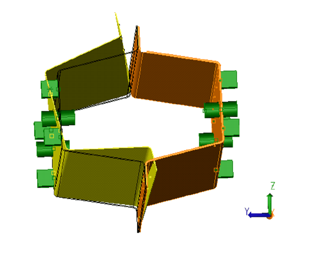
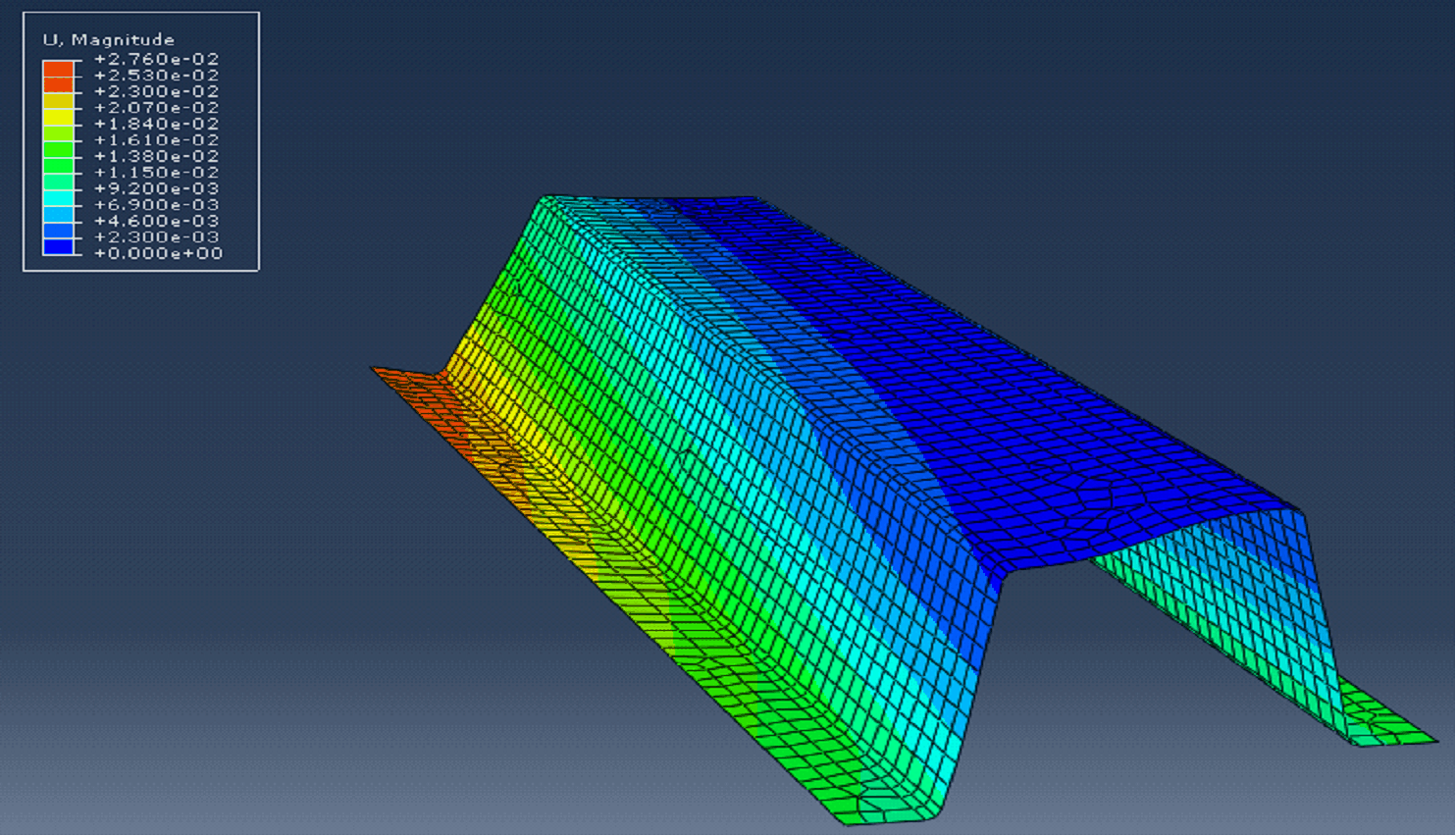
This feature is used to generate the color map of any part in deformed position at any stage in the assembly.
Requirements to run a Global Displacement:
| 1. | Mesh and Stiffness files for the part. |
| 2. | Load FEA Move for the part. |
| 3. | At least one compliant move to deform the part (clamp, force, joining, defomorphing). |
| 4. | FEA software to import the mesh file and to generate the color map. |
Steps:
| 1. | Import the Mesh and Stiffness files using Load FEA move |
| 2. | Deform the Part using any compliant move. |

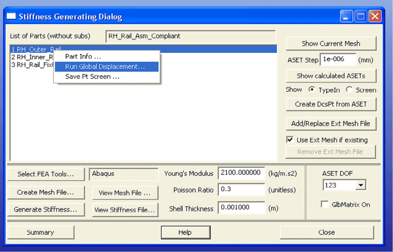
| 3. | Open StiffGen, right click on the part you need the color map and click Run Global Displacement |

Note: Since currently we support only Abaqus to run the Global Displacement, the FEA Tool selected should be Abaqus.
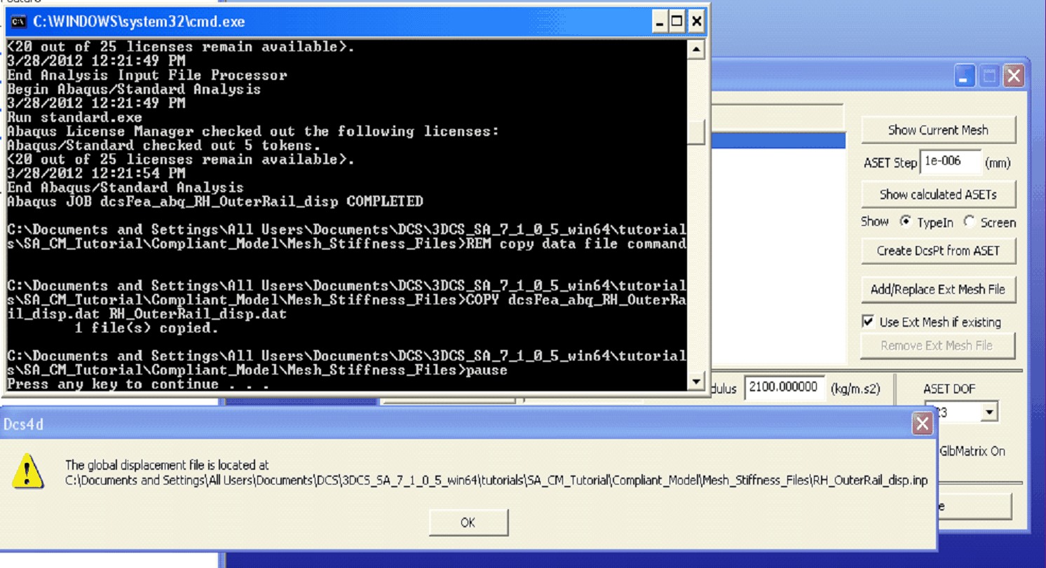
| 4. | It will run through Abaqus and generate a mesh file with displaced nodes. |

| 5. | Import the *.inp file generated in FEA software and run the analysis to create the color map. |
