The purpose of the
Since the Pattern Rigid Move is only locating in the secondary and tertiary directions, a preliminary move is needed to move the object part(s) to the target part(s) in the primary direction. This can be done with most of the moves in 3DCS, for example the Three-Point move. The preliminary move should come immediately before the Pattern Rigid move in the Move list. |
|
See Also: |
Example Models:C:\Users\Public\Documents\DCS\3DCS_V5_8_2_0_0\3DCS CAD & Example Models\Reference Models\Moves\Pattern Rigid move |
Feature Tab:
This move has four types: Fixed-Fastener, Float-Fit-Fastener, Float-Pin-Fastener, and Float-Hole-Slot-Pin. The behavior of the move will differ depending on the type selected.
The number of Object Features must match the number of Target Features because the move works in pairs. For example, the second Object Feature will align to the second Target Feature. Coaxial pairs of features may be selected. All the features will be projected into the same plane, however, when they are aligned to each other.
Fixed-Fastener
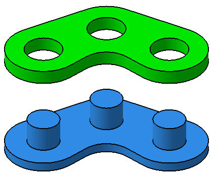
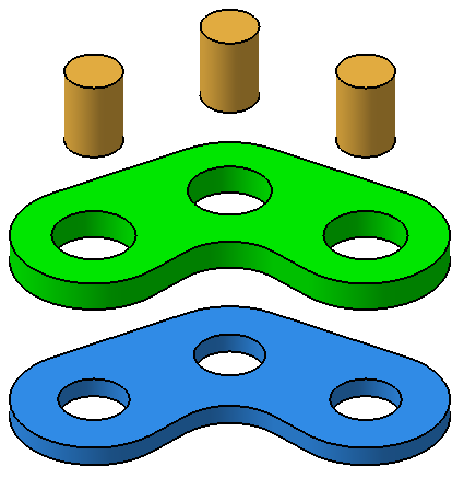
This Pattern Move type will align a pattern of holes and/or pins to a corresponding pattern. For each pair of features, one must be a hole and the other a pin. Pins are assumed to be fixed relative to the part or sub-asm they are in (for example, a bolt is "fixed" in a threaded hole). The Object Features may contain holes, pins, or a combination. The Target Features will contain the corresponding types.
The Object Part(s) will float relative to the Target Part(s) using the clearance between the holes and pins. The patterns will be floated relative to each other according to the Float Mode (Options tab) selected by the user.
Object Features: Holes and/or pins in the Object part(s).
Target Features: Mating features in the Target part(s). Each Target Feature must be the opposite type of the Object Feature. For example, if the fifth Object Feature is a pin, the fifth Target Feature must be a hole.
Pin Features: This field is disabled for this type and should remain empty.
Float-Fit-Fastener (Max Opening)
This Pattern Move type will align a pattern of holes in the Object Part to a pattern of holes in the Target Part while trying to maximize the virtual clearance through each pair of holes. Pins are optional for this type. If pins are used in the move, they will set the minimum limit of the virtual clearance when the move is trying to align the hole patterns. The number of pins selected will determine which of the three different cases (as described below) for this type applies.
Because this type is trying to maximize the virtual clearance, the assembly will have less variation compared to the same move set to the Float-Pin-Fastener type. During deviation, if the two hole patterns are aligned well enough such that the clearances through the holes are already at their maximum, the Object Part will not float on the Target Part. If pins are used, they are placed between the centers of the two holes attached with each pin.
Object Features: Holes in the Object part(s).
Target Features: Holes in the Target part(s).
Pin Features (optional): Pins that will pass through the holes of the Object and Target parts. The pins do not need to be in separate parts. If points are selected as the Pin Features, only the points will be moved into the holes. If surfaces are selected as the Pin Features, both the feature mesh and any points on the surface will be moved into the holes. The CAD part will not move in either case.
The relative number of pin features added to the move will determine how the move will build. Three cases are possible:
Case 1: Two sets of holes only, no pins
The move will try to maximize the clearances at all pairs of holes. This scenario is typically applied to determine the possible sizes of fasteners. In both Nominal Build and the simulation, the move will find the maximum clearances with an algorithm that uses the Open Increment and Iteration Number values set in the Options.
Case 2: Two sets of holes with a pin for each pair of holes
The move will align the object part(s) at the first two pairs of holes. It will then move the pins to the centers of the pairs of holes. If some of the pins do not fit into their corresponding pairs of holes, then the move will shift the object part(s) to maximize the virtual clearance at all the pairs of holes. If some of the pins still do not fit after shifting the object part(s), then the move will find the best fit based on the Open Increment and Iteration Number values set in the Options.
Case 3: Two sets of holes with pins for some of the pairs of holes
The move will try to maximize the clearances at all pairs of hole without pins defined while floating at the pairs of holes with (pilot) pins defined. If the clearances are not maximized at the holes without pins, the parts will be aligned based on the Open Increment and Iteration Number set in the Options similar to Case 1.
Float-Pin-Fastener
This Pattern Move type will align a pattern of holes in the Object Part to a pattern of holes in the Target Part using the clearance between the holes and pins. Pins are required for this move type. Each pair of holes is assumed to have a pin selected. If not, a pin with a diameter of zero is assumed and error messages will appear.
When deviating, the move will use the clearance between the pins and holes to float the Object Part on the Target Part. The floating variation will be similar or the same to the variation from using the Partial Pin Technique. The model will have more variation compared to Float-Fit-Fastener.
Pin Features: Pins that will pass through the holes of the Object and Target parts. The pins do not need to be in separate parts. If points are selected as the Pin Features, only the points will be moved into the holes. If surfaces are selected as the Pin Features, both the feature mesh and any points on the surface will be moved into the holes. The CAD part will not move in either case.
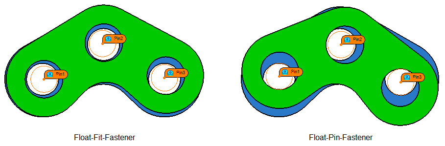
Float-Fit-Fastener vs Float-Pin-Fastener
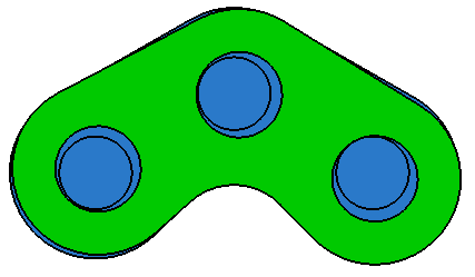
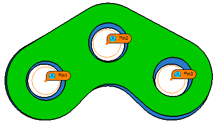
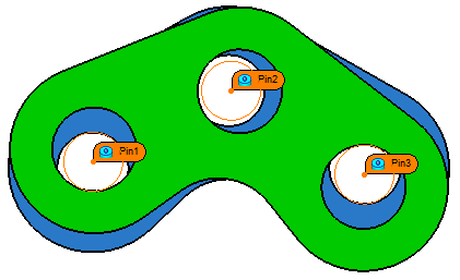
When the Float-Fit-Fastener type has pins for every pair of the holes, the difference between Float-Fit-Fastener and Float-Pin-Fastener will be in the variation. Float-Fit-Fastener is trying to maximize clearances so it will have less variation in the compared to Float-Pin-Fastener, which is floating the Object Part using the full clearance between the holes and pins. The difference is shown in the image below. Notice how Float-Fit-Fastener has still clearance around the pins while Float-Pin-Fastener has contact at Pin1 and Pin3.
Float-Hole-Slot-Pin
This Pattern Move type can fit simultaneously: slots into tabs, pins into slots, or pins into holes. When using slots it should be used to locate on the slot's width not on its length.
It can be used as a fixed or a floating fastener type of move.
•The fixed fastener type will align a pattern of holes and/or slots to a pattern of pins/tabs. For each pair of features, one must be a hole or a slot and the other a pin or a tab. Pins are assumed to be fixed relative to the part or sub-asm they are in (for example, a bolt is "fixed" in a threaded hole). The Object Features may contain holes, slots, pins, tabs, or a combination. The Target Features will contain the corresponding types.
•The floating fastener type will align a pattern of holes and/or slots in the Object Part to a pattern of holes and/or slots in the Target Part using the clearance between the holes/slots and pins/tabs. Pins/tabs are required for this move type. Each pair of holes/slots is assumed to have a pin/tab selected. If not, a pin with a diameter of zero is assumed and error messages will appear.
Object Features: Holes, slots in the Object part(s).
Target Features: Holes, slots in the Target part(s).
Pin/Tab Features (for the floating fastener case): Pins that will pass through the holes of the Object and Target parts. The pins do not need to be in separate parts. If points are selected as the Pin Features, only the points will be moved into the holes. If surfaces are selected as the Pin Features, both the feature mesh and any points on the surface will be moved into the holes. The CAD part will not move in either case.
Pattern Move tabs and functions:
Direction Tab: Directions: The object part will be floated in the plane normal to this direction. If AssocDir is selected, the direction of the first Target feature is used.
•Align Plane: This option will translate the object part until it aligns the first object feature to the first target feature in the Pattern's direction (direction can be set with the available Dir. Type options), thus setting the primary plane of the object part(s). This way the move controls all six degrees of freedom of the object part(s).
Options tab:
Open Increment: Used in combination with the Iteration Number. The type determines how the Open Increment is used.
•Fixed-Fastener: When the hole and pin patterns cannot fit together, the holes are increased in by the Open Increment. All holes are increased in size. The new larger holes are then checked for fit. If it still does not fit, the hole are increased in size again. The hole sizes are increased until a fit is found. The change in hole size required to fit the pattern of pins in the pattern of holes is reported in the Run Log after Run Analysis. The Iteration Number is the maximum number of times the holes will be increased in size. If the Iteration Number is reached and the hole and pin patterns still cannot fit together, a 'No Solution' is reported in the Run Log. The last position of the Object Part will be used in the model even if the patterns cannot fit together.
•Float-Fit-Fastener and Float-Pin-Fastener: When trying to fit the hole patterns together, the move will increase the hole size by the Open Increment. It will then test if the virtual clearance through each pair of holes has been maximized. The hole sizes will be increased by the Open Increment until the virtual clearances have been maximized. If pins are used, the pin size will limit the virtual clearance requirement that the move is trying to meet. The Iteration Number is the maximum number of times the holes will be increased in size. If the Iteration Number is reached and the virtual clearances between the hole patterns still have not been maximized, the Run Log will report "Fail to max clearances with - iter num = ...".
Iteration Number: Used in combination with the Open Increment when the hole pattern does not fit. The Iteration Number is the number of times the move will increase the hole size by the Open Increment, trying to find a solution in a possible no-build sample.
Float Mode: The Float Mode is only available for the Fix-Fastener, Float-Pin Fastener, and Float-Hole-Slot-Pin move options (not available for the Float-Fit Fastener). The Magnitude and Angle approach to floating pins and holes does not apply to the Pattern Move. Instead the move will compute the range of rotation angles that will allow the object to be assembled to the target. If there is no angle that permits assembly, a no-build condition exists. The move will then construct a probability distribution for the rotation angle based on the relative likelihood of successful assembly at each angle in the range. If the user selects Float Mode = Min-Max, a Min-Max distribution is assigned to the rotation angle instead. A rotation angle is then selected from its distribution. Finally, a translation vector is selected that will move the rotated object to the target. The Float Mode controls the way in which the vector is chosen:
•Regular: All possible translation vectors will be equally likely.
•1 Edge: All translation vectors that cause contact between at least one pin and hole will be equally likely.
•2 Edge: All translation vectors that cause contact between at least two pins and holes will be equally likely.
•Min-Max: The maximum rotation in either the clockwise or counterclockwise direction will be equally likely.
Move Parts tab: All object parts or sub-assemblies must be added to the Move Parts lists. Take care that a part is not included twice in the part list (both as itself and as part of a sub-assembly) as it will be moved twice. Parts may be automatically added based on the object points selected in the move.
Failed Builds - Run Log If a no-build condition exists, Pattern Move will report the "no builds" during Nominal Build and Assembly.
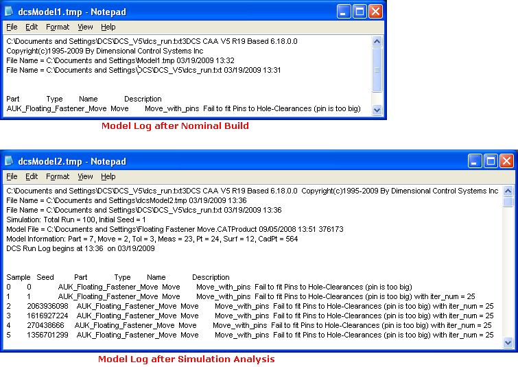
For no-build (failed) assemblies during simulation, the Pattern move will increment the hole size and will write the passing diameter to the log file.
For the Fixed-Fastener Type, the move will use the Iteration Number and Open Increment values to find an estimated best fit location and move the part(s) to this location. If no best fit position is found, the part(s) revert to their previous location.
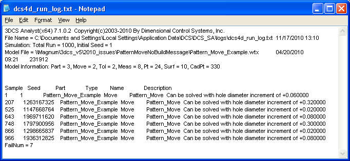
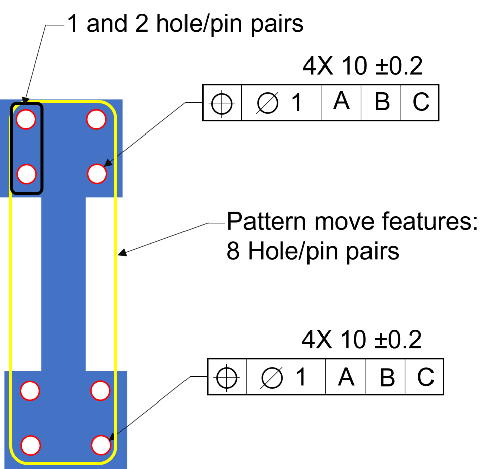
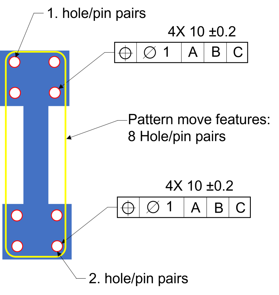
Use of the Pattern Move, 3DCS is solving to fit all hole/pin pairs. With Contributor Analysis, the Pattern Move will use the first two hole/pin pairs to check the tolerances and deviation. (70817)
The total reported Range will be the same between both cases. Fig.2 will list all the details of the two separate position tolerances.
|
|---|
Notes•Directions: oIf the first Target feature is a Slot or Tab, the direction will be incorrect. Change the direction, in the directions tab, to be normal to the move Plane. •When the Pattern move fails, the move will attempt to Best Fit (minimize the interference) with the object and target part(s). You will need to include Failed Assemblies in the Simulation. •The opening between a pair of holes can never be larger that the smallest hole. •The accuracy will only be as good as the Open Increment value. •The smaller the value used for Open Increment, the longer the model may run to find a max opening. •The axis of the holes and pins are assumed to be parallel. •Please note that the use of this move can impact the Contributor Analysis and GeoFactor Equation-Based results. |