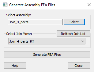
The ability to scale up or do a large model with Compliant Modeler can become a challenge. Depending on the number of compliant moves and other factors, CM can run into computing limitations. To get around this issue, a new function is added to the Compliant Modeler that outputs the files for a lower level model to be then used as black box inputs for a higher level model. In other words, now a compliant model can output dcsFEA files for a fully Joined assembly (mesh file, reduced stiffness matrix, and mass matrix) that can then be used in the Load FEA Data in the next higher level model.
The user can chose which Join moves will be included when the Assembly FEA Files are generated. All the other moves present in the model (Gravity, Force, Thermal or even rigid moves) will affect the assembly mesh node locations. They can be applied before or after the selected Join move.
|
Here is an example for a compliant black box model. This three parts model can be split as shown below:

Then, the results of Model 1 can be incorporated into Model 2 by treating the Sub Assy as a single part with its own FEA files:

To generate assembly FEA files for a model, follow this procedure:
•Launch the ![]() Generate Assembly FEA Files function which will show a list of the active join operations in the model.
Generate Assembly FEA Files function which will show a list of the active join operations in the model.

•Select the last join move or compliant pattern move to be included (the matrices will be created for all the parts joined at that stage). The 'Select Join Move' selection means that the generated FEA files will be based on the selected Join move and all preceding Join moves in that assembly.The 'Refresh Join List' button can be used to update the list of active join moves.
•Click the Generate FEA Files button (the user may be prompted to Nominal Build the model). The Assembly FEA files will be saved in a folder called AssemblyFEAFiles; this folder is at the same location as the model used to create the files.
▪ To generate the correct files, the Nominal Build should be executed every time the join moves are activated/deactivated.
•Create a new model that includes the assembly from the first model, treated as a single part.
•Use the function ![]() Coordinate Points From Mesh to add all the assembly mesh points to the assembly part.
Coordinate Points From Mesh to add all the assembly mesh points to the assembly part.
•Create a Load FEA Data move and load the new created assembly mesh, stiffness, and mass files.
Assembly mesh file description
For a two-part assembly the assembly mesh file will include the following nodes: every node used as ASET for each part except for the joined pairs. At the joined pairs there will be one node that comes from the Object part. Also only the first 3DCS point will be output as Assembly node if there are more than one 3DCS points linked to the same ASET.(74918)
[Number of ASET nodes on 'Part A'] + [Number of ASET nodes on 'Part B'] - [Number of node pairs used in the Join moves]
For example:
Part 1 has 6 nodes.
Part 2 has 6 nodes.
The join operation includes 2 nodes from each part.
The Assembly mesh file will have 10 nodes.
Assembly matrix files description
•The stiffness matrix will be generated for all nodes included in the Assembly Mesh file.
•The mass matrix will be generated for all nodes included in the Assembly Mesh file, only if Gravity move is present and active in the model.