In this lesson we will be calculating the Gear Backlash Angle. We will be using the Gear Modeler to generate the Moves and Measures required for this calculation.
Gear Modeler Inputs
Open the ![]() Gear Modeler dialog by clicking the Gear Icon from the Mechanical Add-On Tab.
Gear Modeler dialog by clicking the Gear Icon from the Mechanical Add-On Tab.
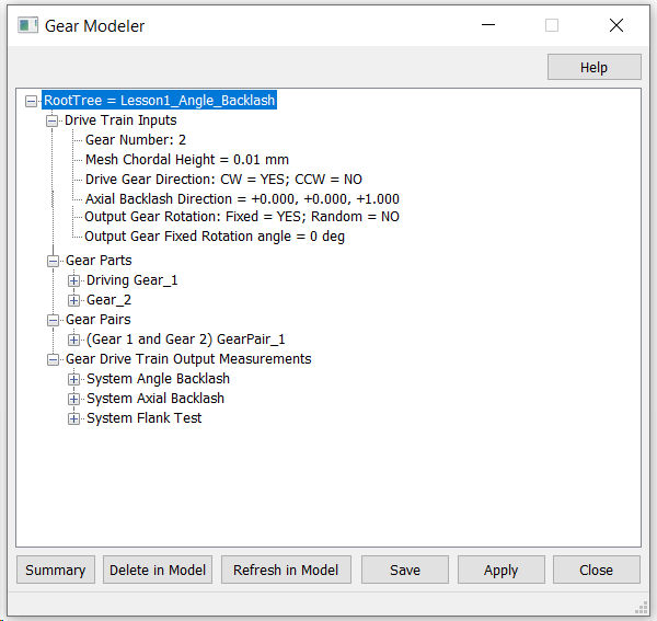
Drive Train Inputs
• Right click the Drive Train Inputs option to add all the inputs under this section.
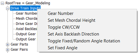
•First select the Gear Number from the menu and set the Gear number to 3
•Similarly you can right click and change the Mesh Chordal Height , Toggle the Drive gear direction and set the Axis direction. For this Tutorial we can set the chordal height in its default value 0.01.
•Leave the Drive direction to Be Clockwise
•Axial Backlash direction not needed at this moment.
•Leave the Output Gear Rotation to Fixed.
•Set the Output Gear Rotation value to 5 degrees.
Gear Parts:
Need to select the Driving Gear and Gear Points.
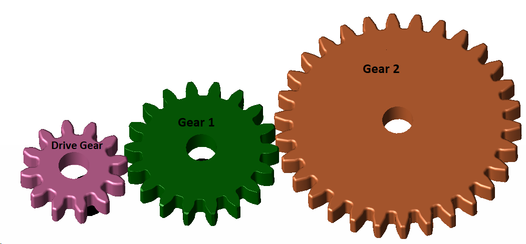
•Under the Gear Part Section the input shows for 3 Gears, Driving Gear_1, Gear_2 and Gear_3. This changes depending on the input number we specified under Drive Train Inputs.
• Select the first smallest Gear to be the driving Gear by adding its information under Driving Gear_1 section
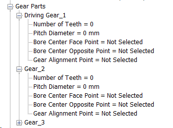
• Right click the Driving Gear_1 to add the inputs.
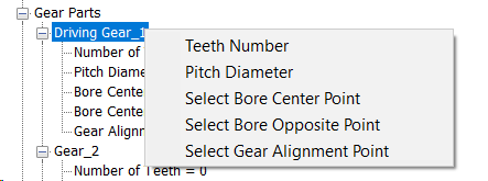
•Enter the Teeth Number =12
•Pitch Diameter not required at this moment
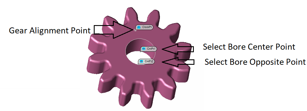
•Click "Select Bore Center Point" and select the CntPt1 from Gear1 when the selection dialog pops up
•Click "Select Bore Opposite Point" and select the CntPt2 from the Gear1.
•Select "Gear Alignment Point" and select the ClockPt from Gear1.
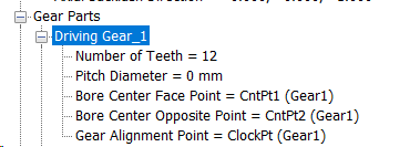
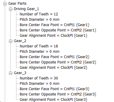
The Completed Tree should look like the image below,
Repeat the steps on Gear 2 and Gear 3
Gear Pairs
The Gears Gear 1 and Gear 3 used in this Tutorial model have multiple surfaces in the Gear Teeth, for this case these multiple surfaces need to be combined first to make a single Surface before adding them to the Gear Module.
Creating a Combined Feature:
• Click the drop down arrow next to Dynamic Mid Point button and select ![]() Combined Feature.
Combined Feature.
• Select Gear1 when the selection dialog pops up.
• Now click Create from the dialog and start picking the three surfaces from the Drive surface of Gear1.
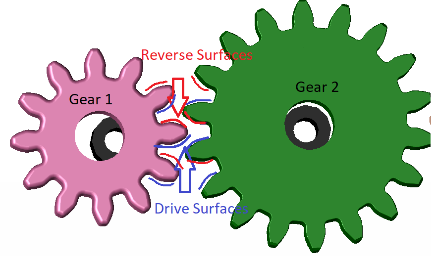
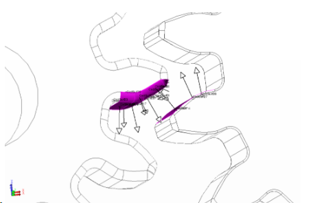
Refer the image below to know the Drive and Reverse Surfaces of Gear 1
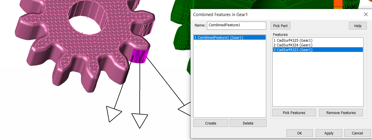
The Combined feature dialog after completing the first Drive face Combined Feature
•With the dialog open click Create again to create the combined feature for the next Drive face.
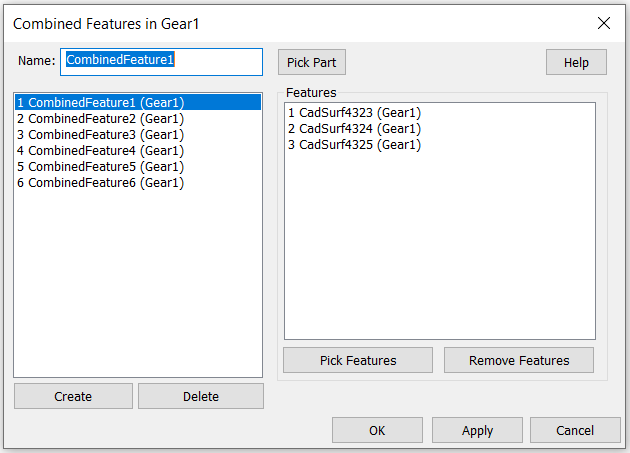
Repeat this step till you create combined feature for all the drive and reverse faces.
The complete dialog should look like below,
•Hit Ok to close the dialog
•Repeat the same steps to create combined features for Gear 3 also.
•The created Combined feature will list in the tree under feature list of each part.
Gear Pairs Selection in Gear Module
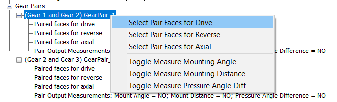
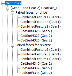
• Under the Gear Pairs section right click the 1st pair option to add the pair faces for drive.
•Now start picking the pair faces of the first Gear part followed by the second Gear part
•Make sure you pick the created combined feature for Gear 1
•Now right click Select Pair Faces for Reverse and start selecting the reverse matting faces of Gear 1 followed by Gear 2
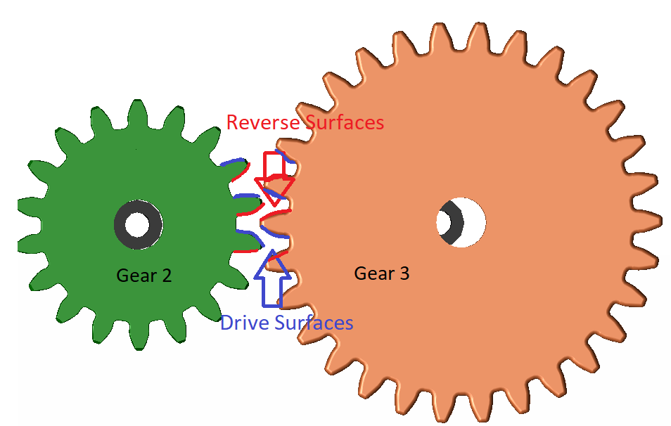
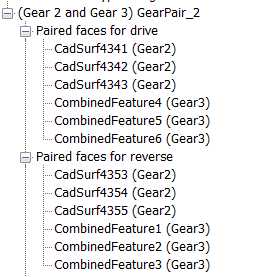
•Repeat this for the second pair (Gear2 and Gear3)
While selecting the pair faces make sure to select all the faces from the first Gear and then switch to the second Gear.
Ignore the Axial Face selection for now.
Gear Train Outputs
• Under the Gear Train Out put section expand the System Angle Backlash.
By default the System Angle Backlash is set to Drive and Reverse.
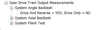
•Leave the Axial Backlash and Flank Test selection set to None.
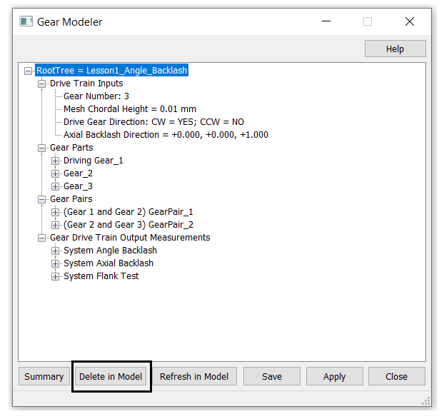
•Click Apply, This will generate the Moves and Measures required to calculate Angle Backlash. The Parts and root will also have some additional points created which will be used in the Moves and Measures
Delete in Model
This command will delete all the data created through the Gear Modeling Utility including Points, Moves and Measures from the Model. Use this only if you make a mistake in the Gear Modeler and select Apply
Created Move Groups
Drive and Reverse Moves will be generated for both Gear Pairs.
•The Moves created will be grouped for better understanding
•In total 4 move groups will be created one Drive and one Reverse for each Gear Pair.
•The initial Two point moves manually created to assemble the Gears to Bearings will also be automatically added inside a Move group
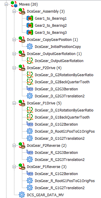
The Saved information from the GUI will get saved to the tree as a dummy move. Adding or editing any information need to be done in the Gear Modeling dialog.
![]()
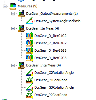
Created Measure Groups
Two Measure Groups gets created. Angle Measure for System Angle Backlash and also a set of Feature measures required for the Iteration Moves gets created. These Feature Measure will have the as "As Output" deactivated.
• Nominal Build to see the model build by applying all the generated Moves.
• Animate to see how each move works step by step.
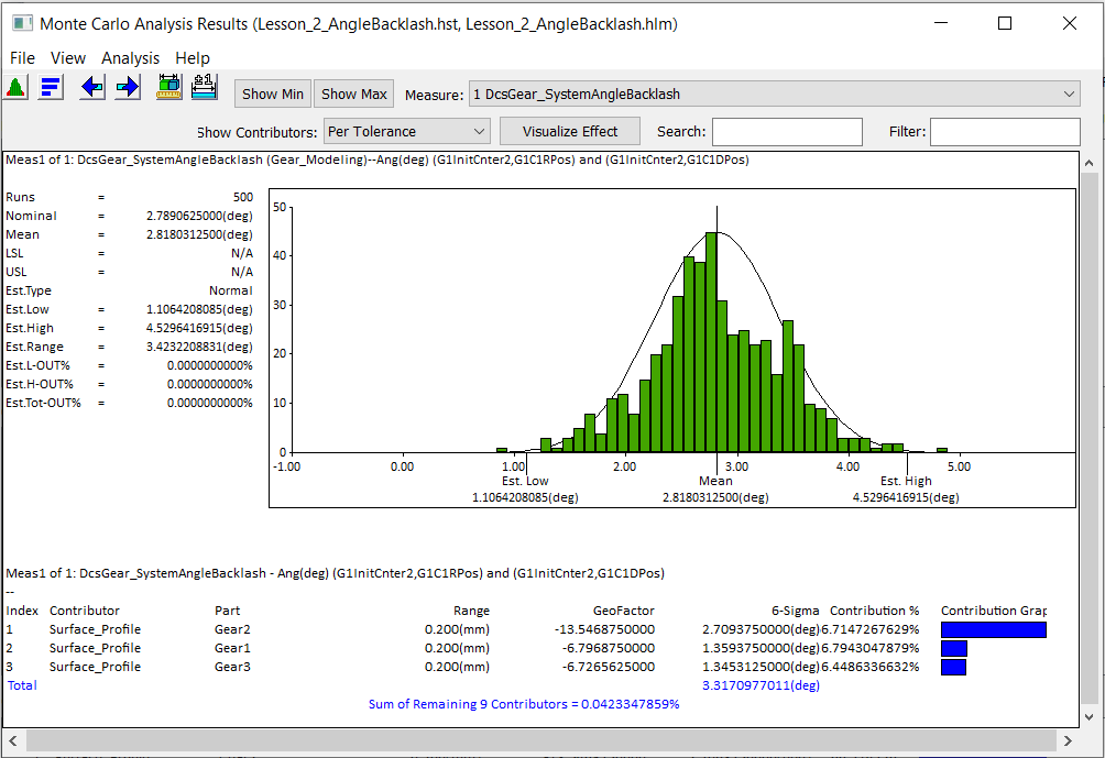
Run Analysis
•Click the Run Analysis function from the Statistical Analysis Toolbar.
•Click the Start button to run 500 samples.
•Save the Model as Lesson2_Angle Backlash.