In this lesson we can see how to calculate Mount Angle, Mount Distance and Pressure Angle for the Gear Pairs
These Measurements are not like the System Output where these applies for each Gear Pairs individually.
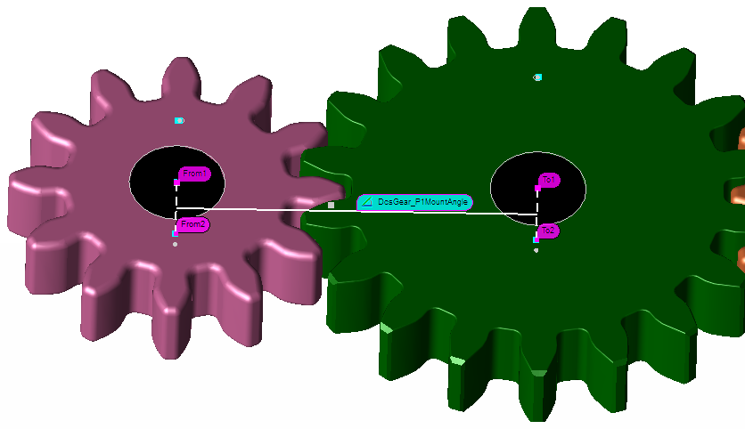
Mounting Angle :- Angle between the Bore Axis of a Gear Pair
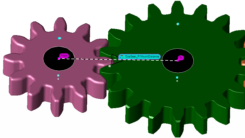
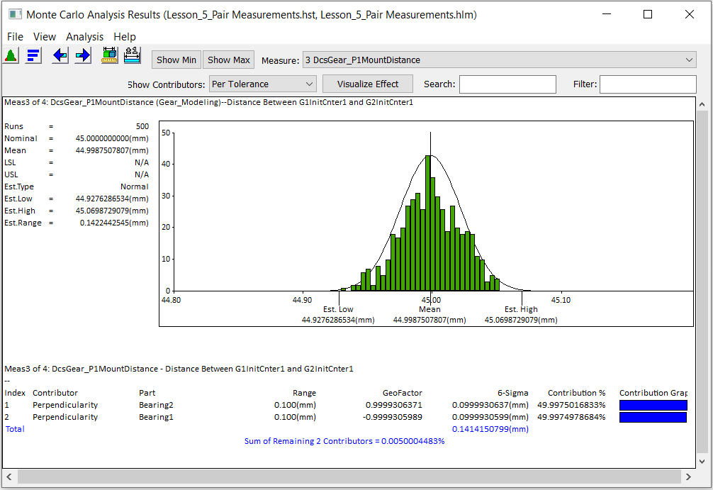
Mounting Distance :- Distance Between the Bore Center Face Points of a Gear Pair
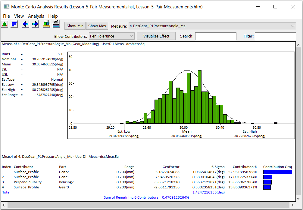
Pressure Angle :- Angle Between the Drive Contact Normal and the Circular Tangent at the Contact Point for the first gear of the pair. Pressure Angle Measure alone requires System Angle Backlash active.
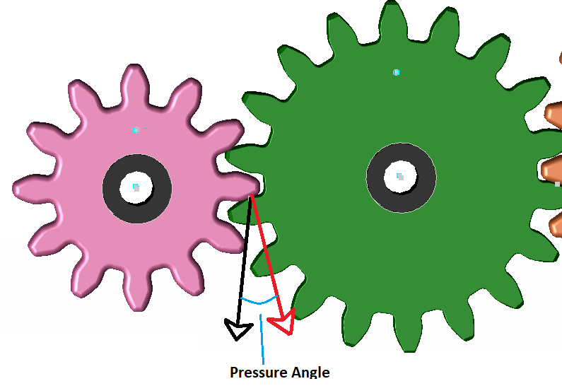
Black Vector is Tangent to Gear1 at the Contact Point of Gear2
Red Vector is normal to the contact surface of Gear1
The Angle between these two vectors is the pressure Angle.
Gear Modeler
•Open the Gear Modeler dialog
•Select Delete from Model to clear the previously created Moves and Measures.
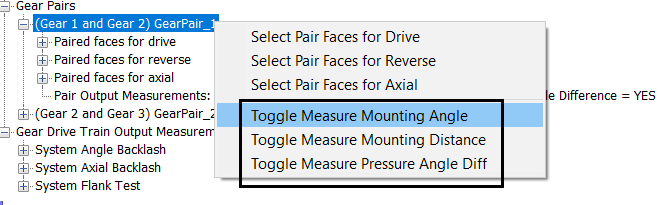
•Right click the First clear pair and toggle Mounting Angle, Mounting Distance and Pressure Angle.
•Repeat the same for the second Gear Pair
•Notice all the Gear Pair Measurements will switch to Yes.
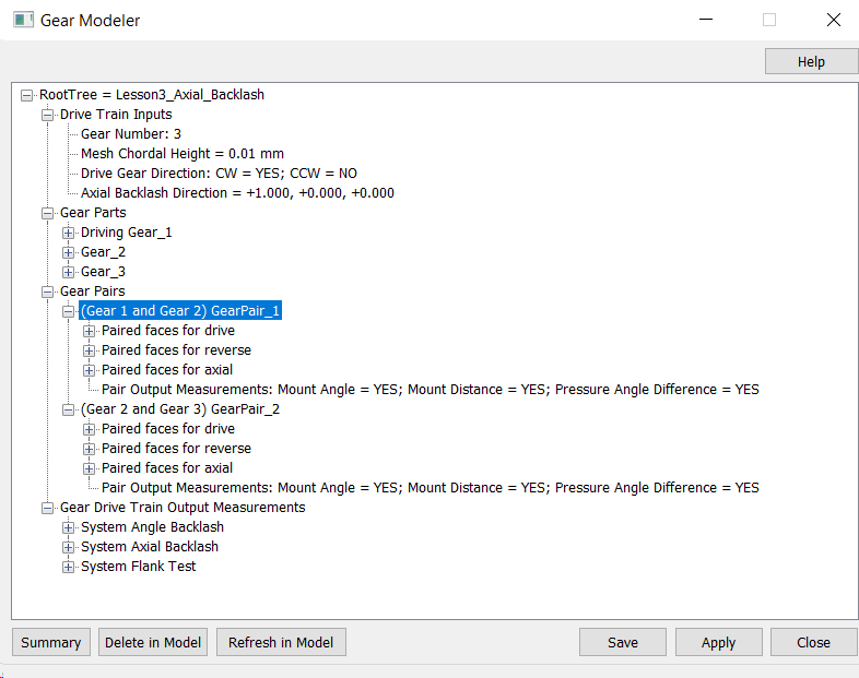
•Leave the System Angle Backlash Output measure in Drive only model
•Click Apply to create the Moves and Measures in the Model.
Pair Measure Moves:
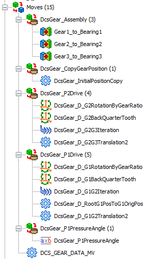
Notice how all the Pair Measurements be created in a separate group folder.
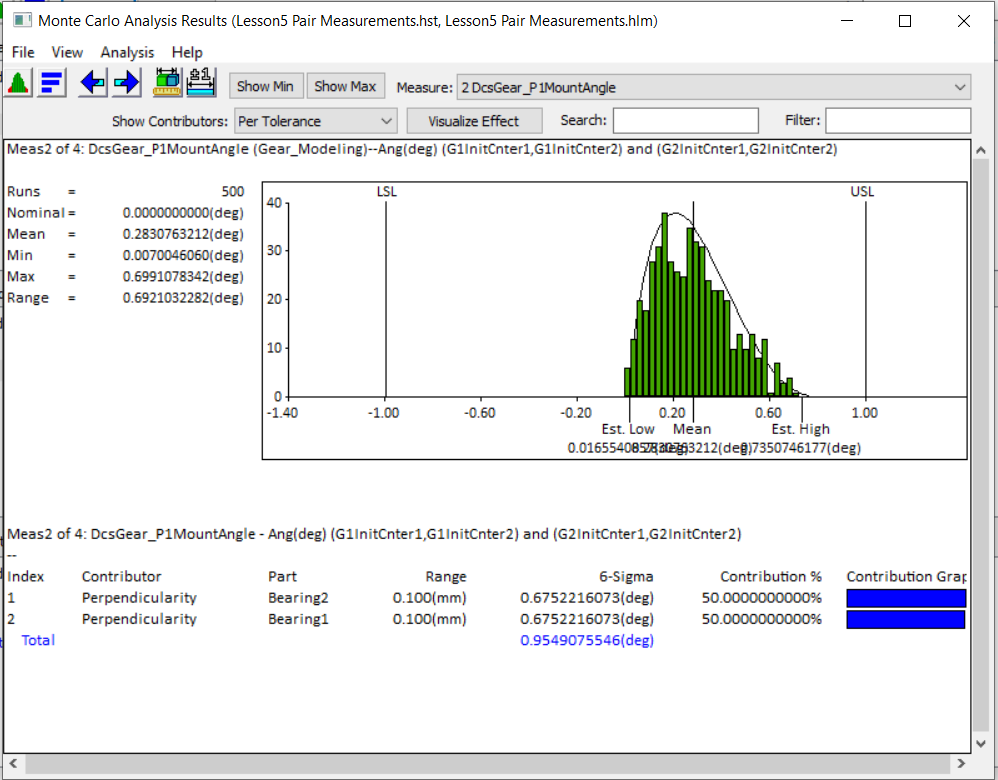
Run Analysis
•Click the Run Analysis function from the Statistical Analysis Toolbar.
•Click the Start button to run 500 samples.
MountAngle Distance
Mount Distance
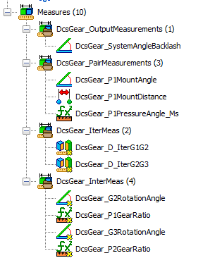
Pair Measurements
•Save the Model as Lesson5_Gear Pair Measurements.