Creating Position, Profile, and other Geometrical tolerances:
1.Click ![]() Feature Control Frame.
Feature Control Frame.
2.[Select Object] under the Associated Objects tab.
3.Under the Frame Tab, select the desired Characteristic as [Profile of a Surface], [Position], etc.
4.Still under the Frame Tab, expand the Tolerance section if not already done. Fill out this section according to tolerance needed.
5.Below the Tolerance Tab, fill out the Primary, Secondary, and Tertiary Datum Reference sections according to what is needed.
6.Below the Frame Tab, fill out the Text tab if needed. The words "<My Feature Control Frame>" that are already in the text box dictates where the feature control frame will be located in relation to the text applied. For example, if text is needed under the feature control frame, type below the original text.
7.Scrolling back up to just above the Frame Tab, there is the Leader Tab. Click Select Terminating Object and click a corner of the surface that the profile should be applied to. If the leader line is desired to originate from the center of the surface, a Point will need to be created. Refer back to Creating Datum Targets to learn how to create a Point for use with PMI.
8.To place the Feature Control Frame after selecting the terminating object, hover the cursor over the display. You may see that the feature control frame may be angled incorrectly. To change this, under the Orientation Tab, select the plane that the feature control frame should be placed in. Then click in the display to place the Feature Control Frame.
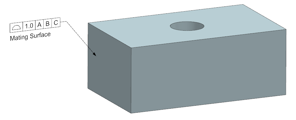
9.The finished Feature Control Frame should like like the image below.
