Procedure:
1.In the PMI Tab, the Dimensions Toolbar allows the creation of different measurements. For this section, we will focus on the Linear and Radial dimensions.
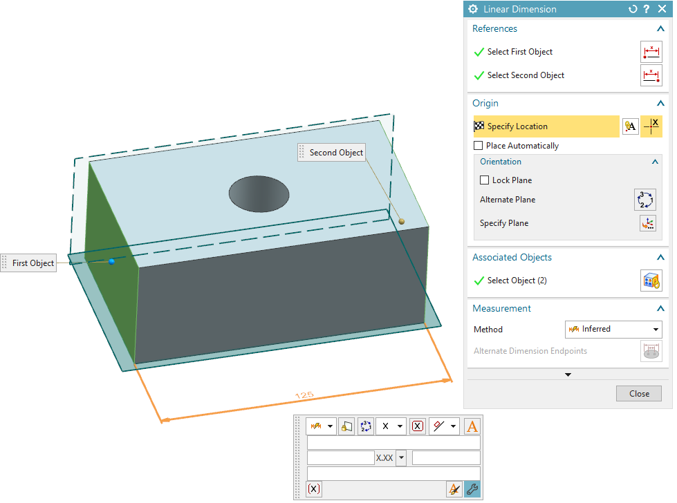
2.First we will look at creating a Linear Dimension. Click![]() Linear Dimension to create a size tolerance on a linear feature like a slot.
Linear Dimension to create a size tolerance on a linear feature like a slot.
3.Once in the dialog box, click both objects that are meant to have a size tolerance on them. Drag the dimension to the desired area. Holding the mouse still will bring up the size tolerance box shown in the image below.
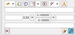
4.To add in the size aspect of the Linear Dimension, click the drop down next to the X. Here the user can select Equal Bilateral, Unequal Bilateral, etc. depending on what is needed. If left as the default X, no size tolerance will be added.
5.Type in the desired size tolerance and place the dimension by clicking in the display.The finished dialog will look like the image below. [Close] the PMI Linear Dimension Dialog.
6.Next we will create a Radial Dimension. Click![]() Radial Dimension to create a size tolerance on a radial feature like a hole or pin.
Radial Dimension to create a size tolerance on a radial feature like a hole or pin.
7.Click the surface of a hole or pin. Drag the dimension to the desired area. Holding the mouse still will bring up the size tolerance box shown in the image below.
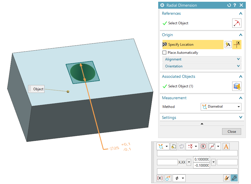
8.To add a size into the radial dimension, we will do the same as above in the Linear Dimension. Add an Equal or Unequal Bilateral tolerance by clicking the drop down menu under the X.
9.Type in the desired size tolerance and place the dimension. [Close] the PMI Radial Dimension dialog.