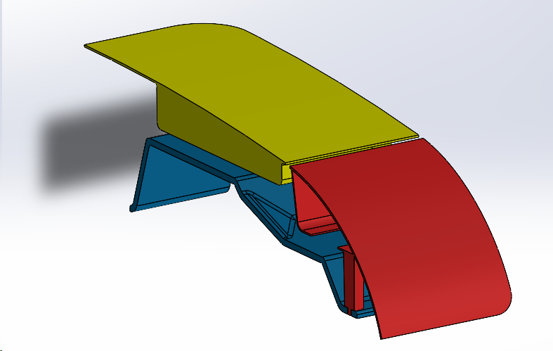
3DCS assemblies can be sectioned off using the Solidworks sectioning tools.
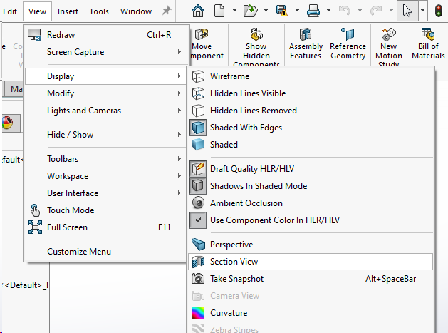
In the part or assembly go to View ![]() Display
Display ![]() Section View
Section View
In the Section View Manager, in the Section Method section choose between Planar or Zonal.
•Planar - Define a section view by selecting one, two or three planes.
•Zonal - Defien a section view by selecting one or more zones. This is used to create section views where multiple areas of the model are cut away.
In the Section Options, select how the section offset is calculated.
•Reference Plane - Values are calculated normal to the currently-oriented section plane.
•Selected Plane - Values are calculated normal to the plane you select in Section 1.
In Section 1 select a plane. Then set the offset distance and rotation.
•If additional planes or faces are needed then select Section 2 and Section 3 and set the properties.
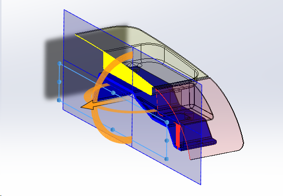
Click Preview to show the graphics-only preview of the section based on the section plane location that was previously selected.
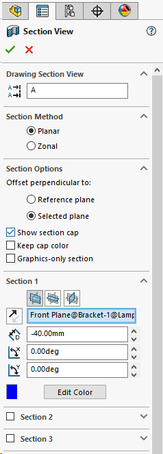
Once everything in the Section View Manager is selected and the set view(s) look right, in the top left corner select the green check mark or OK button.