The ISO Standard comes with multiple Tolerance definitions. Here is a list of features for the ISO/JIS standard and what they mean for 3DCS. |
|
TopicsCommon Zone Composite Tolerance Rule of Independency Median Line/Plane |
References |
Modifiers |
||||
Symbols |
Description |
Standard |
Used in 3DCS |
Notes |
|
MMC/LMC/RFS |
ASME, ISO, JIS |
Yes |
3DCS will not extract or use |
|
Diametrical and Spherical zones |
ASME, ISO, JIS |
Yes |
These symbols define the zone-shape for deviation. |
|
Unequally Disposed |
ASME, ISO, JIS |
Yes |
Users can apply the modifier in 3DCS by applying an Offset. The standard will determine the offset value direction. |
|
Projected Tolerance Zone |
ASME, ISO, JIS |
Yes |
|
|
Envelope |
ASME, ISO, JIS |
Yes |
Applies the Envelope flag to size tolerances. ASME will automatically apply this setting; ISO and JIS can be set or extracted from the PMI, otherwise the Envelope Rule is not applied. Note: When the Envelope flag is activated, the form tolerance will be truncated with in the size tolerance range. |
|
Statistical Tolerance |
ASME, ISO |
Yes |
This modifier cannot be defined in 3DCS and it will not extract from PMI generated GD&T. 3DCS will calculate each tolerances as Statistical Tolerances. |
ASME Standard rules and definitions
Material Condition: The Material Condition 
 can be applied to tolerances in 3DCS. It is required to have a Size Tolerances active on the same features as the tolerance with MMC or LMC.
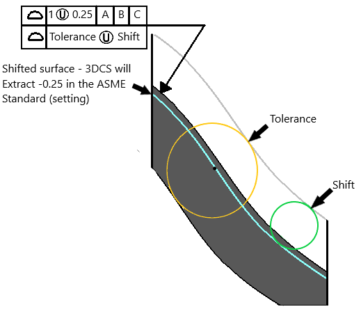
Unequally Disposed

Applying an Equally Disposed offset to GD&T, 3DCS will extract it as an Offset in the Profile tolerance. For the ASME standard, the value is set inward or negative of the nominal surface.
The nominal surface will deviate inward to show the offset and deviate +/- of the n tolerance value.
ISO Standard rules and Definitions
Composite Tolerance: While the ISO or JIS standard is active, 3DCS will not allow these standards to create a Composite tolerance.
Rule of Independency: Generally, 3DCS variation follows the Principal of Independency. Variation is independent unless a relationship is specified, such as by adding an MMC modifier.
The envelope condition, however, only applies to size tolerances on features without a form call-out. In this case, the size variation maintains perfect form by default, thus fulfilling the envelope condition. Generally, the size tolerance can be modified to have form variation and the size variation will be automatically adjusted so the envelope condition is maintained. If form variation is specified in a separate tolerance, such as adding a Straightness tolerance, it will be treated as a separate call-out, meaning the envelope condition does not apply.
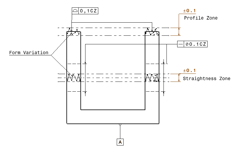
Common Zone: Common Zone for the ISO standard allows the features to deviate within the defined Zone. In 3DCS, Common Zone is applied automatically to the set of features to deviate within a zone and within the defined range. (ref. 65036) More details of Common Zone can be found on the DCS Community.

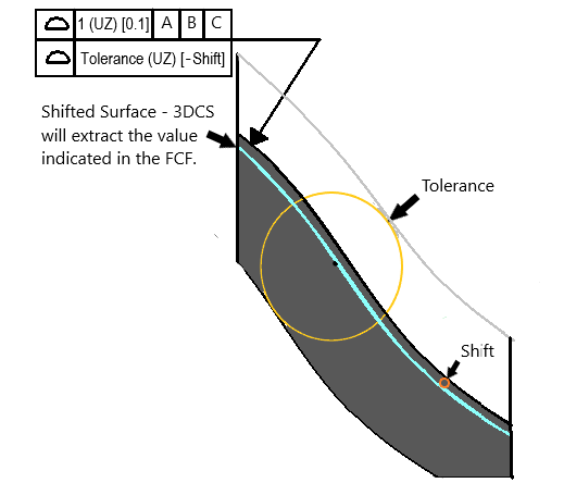
Unequally Disposed (ISO):

Applying an Equally Disposed offset to GD&T, 3DCS will extract it as an Offset in the Profile tolerance. For the ISO standard, the value can be either negative or positive of the nominal surface.
The nominal surface will shift out or in, depending on the shift value, to show the offset and deviate +/- of the n tolerance value. The Unequally Disposed value cannot be larger than the tolerance range.