One input to simulate feature deviation in 3DCS is
|
Creating a New GD&T Procedure:
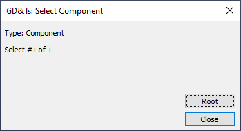
1. Click ![]() GD&Ts from the Model Creation Toolbar then select a part or assembly, or select [Root]. Selecting Root will create the GD&T at the top level assembly.
GD&Ts from the Model Creation Toolbar then select a part or assembly, or select [Root]. Selecting Root will create the GD&T at the top level assembly.
2.This will open the GD&Ts dialog for that part or assembly. In the GD&Ts dialog all previously created GD&T in the part will be displayed in the GD&T List.
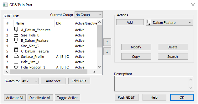
3.Select a GD&T from the list and click on the [Add] button. The GD&T dialog box is displayed.
4.When finished editing the GD&T, select [OK] or [Apply]. The Apply button keeps the GD&T dialog open, allowing you to immediately enter another GD&T. OK will save and close the Tolerance dialog box. The Cancel button exits the dialog without saving it and returns you to the GD&T list dialog.
5.Users can immediately check the tolerance by setting the model to ![]() Nominal Build and
Nominal Build and ![]() Deviate.
Deviate.
Add: Create the selected GD&T type displayed in the adjacent drop-down menu.
Modify: Edit the selected GD&T in the GD&T List.
Delete: Delete selected GD&T from the GD&T List.
Copy: Copy the selected GD&T in the GD&T List.
The GD&T dialog will group a tolerance if an identical Features list appears in multiple different GD&Ts. Datums are not grouped with other GD&T types. Users can ungroup the GD&Ts by going to the Preferences dialog and activating Only edit one GD&T at a time. |
Switch To: Users can move the created GD&T to a new position in the GD&T List.
Auto Sort: Arranges the GD&T List order in the tree and dialog based on the order 3DCS will execute the GD&Ts in when running a Simulation.
Activate All: Activate all of the GD&T in the GD&T List.
Deactivate All: Deactivates all of the GD&T in the GD&T List.
Toggle Active: Switch the selected GD&T in the GD&T List between Active and Inactive.
Push GD&T: Update the CAD parts and assemblies with values from 3DCS. Only applies to values GD&Ts extracted from the CAD parts and assemblies. Will not push the GD&Ts created natively in 3DCS.
Current Group: If any GD&T Groups exist in the tree, only the GD&Ts in the selected Current Group will display in the GD&T List. Any created GD&T will also be added to the Current Group in the tree.
Common Parameters
In the GD&Ts dialog, select a type from the drop-down list (Datum Feature, Size, Position, Surface Profile, etc.) and select [Add]. This will open the GD&T dialog.
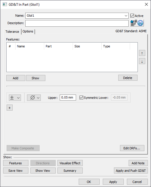
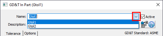
Name: A unique identifier for the GD&T. Cannot have duplicate names within a component. If there are multiple frames, each one must have a unique name. The name for each frame can be selected with the name drop-down.
Description: Optional. A field to provided further information about the GD&T.
Active: Set the GD&T active (checked) or inactive (unchecked).
Features: The list of features that will deviate. Unless specified elsewhere (either in the Options tab or through creating a Composite GD&T) the features in the Features list will vary independently of each other within the range set in the GD&T dialog.
Add: Add features to the GD&T's Features list.
Show: Highlight the features of the GD&T in the graphics.
Delete: Remove the selected features in the Features list from the GD&T.
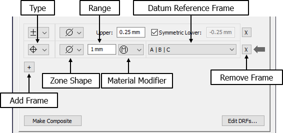
Type: Sets the type of GD&T.
Zone Shape: Sets the shape of the zone the features will vary within. Zone shapes can be:
•empty - Shape of the true surface. Any features in the Features list will vary along the direction normal to their surface. If a ![]() Position GD&T is used with an empty zone shape, a direction may be required in the Options tab.
Position GD&T is used with an empty zone shape, a direction may be required in the Options tab.
•![]() - Cylindrical zone shape. Only diametrical Features of Size are allowed in the Features list when this zone shape is used.
- Cylindrical zone shape. Only diametrical Features of Size are allowed in the Features list when this zone shape is used.
•S![]() - Spherical zone shape
- Spherical zone shape
Note: Not all GD&T types will have access to all possible shapes. For example, a ![]() Surface Profile GD&T can only have an empty zone shape (cylindrical and spherical are not supported) or a
Surface Profile GD&T can only have an empty zone shape (cylindrical and spherical are not supported) or a ![]() Concentricity GD&T can only have a cylindrical zone shape.
Concentricity GD&T can only have a cylindrical zone shape.
Range: The Size of the tolerance zone. (Range = MaxSample - MinSample)
Material Modifier: Modifies the size of the tolerance zone. Can be:
•empty - Regardless of Feature Size - RFS
•![]() - Maximum Material Condition - MMC
- Maximum Material Condition - MMC
•![]() - Least Material Condition - LMC
- Least Material Condition - LMC
Note: Not all GD&T types will have access to the material modifiers. Only GD&T allowed by ASME/ISO/JIO to have material modifiers will have this drop-down available to them.
Datum Reference Frame (DRF): Sets the datum features that the GD&T is relative to. In addition to the Datum Reference Frames created in the Edit DRFs dialog (accessed from [Edit DRFs..] in the lower right of any GD&T dialog), can be:
•No DRF - Used when no datum reference is required, e.g. flatness. When used with profile, this will control form. When used with position, this will control location and act identically to when From Nominal is selected.
•DRF - GD&T will be relative to the selected Datum features. The DRF must be created in the Edit DRFs dialog, accessed from [Edit DRFs..] in the lower right of any GD&T dialog.
•From Nominal - This can be used when a datum reference is required by the type but the user has chosen not to provide one. The features will vary with perfect form relative to their nominal geometry.
Add Frame: Adds another frame for another GD&T to be applied to the same features. For example, the ![]() Size and
Size and ![]() Position GD&Ts can be created on a hole within the same dialog. Even though multiple single-frame GD&Ts may be shown in a single dialog, the tree will show each GD&T as an individual item. Each frame has its own name which must be unique in the parent component.
Position GD&Ts can be created on a hole within the same dialog. Even though multiple single-frame GD&Ts may be shown in a single dialog, the tree will show each GD&T as an individual item. Each frame has its own name which must be unique in the parent component.
Note: Up to 4 GD&T Frames will show at a time in the GD&T Dialog that shares the same Feature, adding more than 4 frames will require a new GD&T dialog. There is a setting in the Preferences dialog to show one GD&T at a time which will not group the GD&T for identical Features lists.
Remove Frame: Removes the selected frame. Only available when the dialog is displaying multiple frames.
Make Composite: Adds a composite frame. Only available for ![]() Position,
Position, ![]() Surface Profile, and
Surface Profile, and ![]() Line Profile. Composite GD&Ts are considered a single entity in 3DCS. Thus, they appear in the tree as a single item and only have one name.
Line Profile. Composite GD&Ts are considered a single entity in 3DCS. Thus, they appear in the tree as a single item and only have one name.
Edit DRFs...: Opens the Edit DRFs dialog to allow the user to create or edit DRFs in the part or assembly.
Save View: Save the current orientation of the graphics for the image in the report.
Show View: Show the saved orientation in the graphics.
Visualize Effect: Deviates the model only for the selected GD&T. See Visualize Effect.
Summary: View information about the GD&T.
Add Note: Add text or images that will be included in the Report.
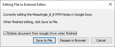
•If using Google Docs, edit the notes, return to 3DCS and select [Save to File] button.
oDelete document from Google Drive when finished - removes the Doc from the user's Google Drive.
Notes:
•When creating a new Note or Editing a Note within any MTM or GD&T dialog, Word will open. Once the user closes Word or the External Editor dialog, the HTML will be saved in the correct format and saved with the model. Users can Close Microsoft Word with the Notes and Images, but will need to select Yes and Yes: first to save the Note and Image to the dcstemp.htm and Yes to save the correct HTML format.
OK: Save the GD&T and close the dialog.
Apply: Save the GD&T.
Cancel: Close the dialog without saving changes.
Notes:•Using the GD&T and GD&T Measure dialogs, any GD&T or Measures with identical Features lists used will show all GD&T or Measures in the dialog as different frames. Users can edit this option in the Preferences dialog and toggling the "Only edit one GD&T at a time" option. Additionally, any GD&T that is inactive will be hidden from the dialog. •When using points in the GD&T features list, each point will be defined as its own individual feature. |