3DCS has two Translate/Rotate functions available. The Component function will modify the current position of a part or assembly.
The Points function will modify the nominal positions of a set of points.
ComponentThis function translates the part along a line or in the X, Y and/or Z axes. It can also rotate the part about a line or about the X, Y and Z axes. The translation and rotation change the orientation of the part for visual display only. It does not affect any of the moves, tolerances or measurements associated with the part. This is a valuable tool to use when working with the model because the parts can be viewed separately without requiring any moves.
|
Procedure:
1.Go to the Geometry tab and Translate/Rotate ![]()
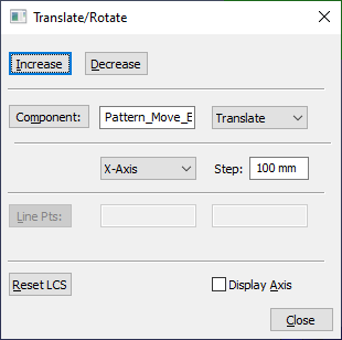
![]() Component. This will open the Translate/Rotate dialog box.
Component. This will open the Translate/Rotate dialog box.
2.Select the Component button in the dialog. This displays the name of the part next to the Component button.
3.Select the method to be set: Translate or Rotate.
4.Select the [Direction] of the part to be rotated or translated. The part can be translated/rotated in X, Y or Z direction, or also Along a Line.
oIf the Line direction is used, the [Line Pts] button is now activate. Click the [Line Pts] and select two points. The user could also manually type in the name of the points in the text boxes.
5.Step is the distance of translation and the angle of rotation. The default translation is 100 and the default rotation is 5.0 (measured in degrees).
6.Translate the part towards the origin along the selected axis and rotate the part in the clockwise direction about the selected axis by clicking the Decrease button.
oThe [Increase] button translates the part away from the origin along the selected axis and rotates the part in the counter-clockwise direction about the selected axis.
7.[Reset LCS] will reset the Local Coordinate System of the selected part. This brings the part to its nominal position and any Translation or Rotation is lost. The Local Coordinate System (LCS) is the coordinate system that is established when parts are translated or rotated from their nominal position.
Procedure:
•Click on Edit ![]() Translate / Rotate. Select the component whose coordinate system is to be reset. A conformation dialog box with the name of the part is displayed, stating that the LCS at the root level will be lost.
Translate / Rotate. Select the component whose coordinate system is to be reset. A conformation dialog box with the name of the part is displayed, stating that the LCS at the root level will be lost.
•Clicking on Yes will undo all translation and rotation to the part. The part will be at its nominal position after LCS has been reset. Clicking on No will escape the dialog box back to the Tree window.
Note: You can reset an assembly - this will reset the part and it's sub parts.
8.Click on [Close] when finished.
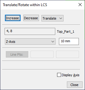
Points: This function will modify the type-in positions of a set of points.
1.Go to the Geometry tab and Translate/Rotate ![]()
![]() Component.
Component.
2.This will open the Translate/Rotate dialog box. A point selection dialog will appear.
3.Select the desired point(s) and [Close].
4.Select either Translate or Rotate and specify the direction and increment.
5.Use the Increase and Decrease buttons to modify the point coordinates.
6.Select [Close] to exit.