Unit Basis (often called Rate of Change) is available in the Options tab of the GD&T dialog for any form tolerance. This includes: ![]() Flatness,
Flatness, ![]() Straightness,
Straightness, ![]() Surface Profile (No DRF), and
Surface Profile (No DRF), and ![]() Line Profile (No DRF).
Line Profile (No DRF).
Adding Unit Basis to GD&T Procedure:
1.In the GD&T dialog for an applicable GD&T and select the Options tab.
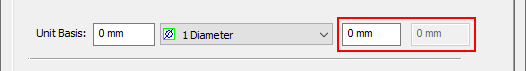
2.In the Unit Basis section, enter the Zone Range in the first text entry field.
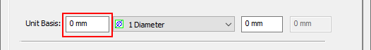
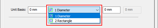
3.If applicable, select the Zone Shape from the neighboring drop-down.
4.Select the Zone Size in the final one or two text entry fields (depending on Zone Shape there may be one or two text entry fields available here).
How Unit Basis Varies the Feature:
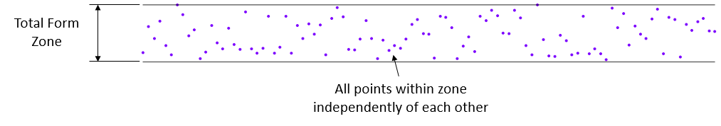
Unit Basis adds a refinement to a form GD&T such that neighboring nodes/points won't deviate completely independently of each other. With Unit Basis set to zero, 3DCS will treat it as if Unit Basis is turned off and each node/point will vary independently, such as in this image with a series of points and a ![]() Flatness GD&T.
Flatness GD&T.
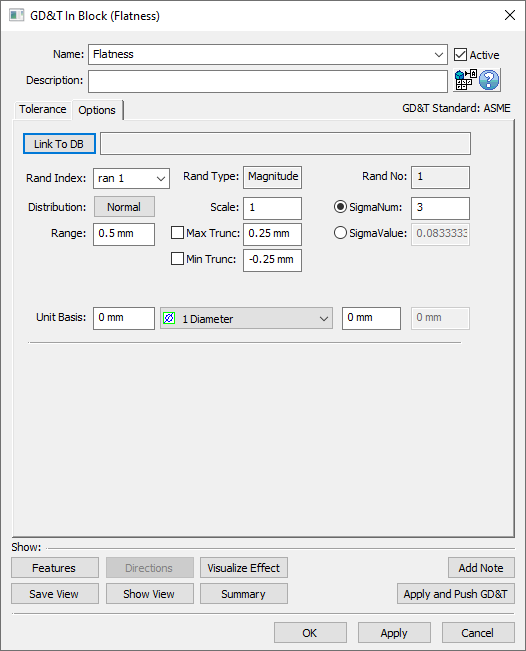
Adding a Unit Basis will change how 3DCS treats this form tolerance. For a line of points like this, the points will be given a relationship to each other and be treated as a line with slope that is less than the Unit Basis Zone Range divided by the Unit Basis Zone Size (rise over run). If at any point the line will leave the Total Form Zone then the direction will be flipped and it will begin traveling in the other direction with the same slope, but this time rising instead of dropping (or dropping instead of rising). The image below shows the same surface with ![]() Flatness GD&T applied to it, but this time with a Unit Basis input also used.
Flatness GD&T applied to it, but this time with a Unit Basis input also used.
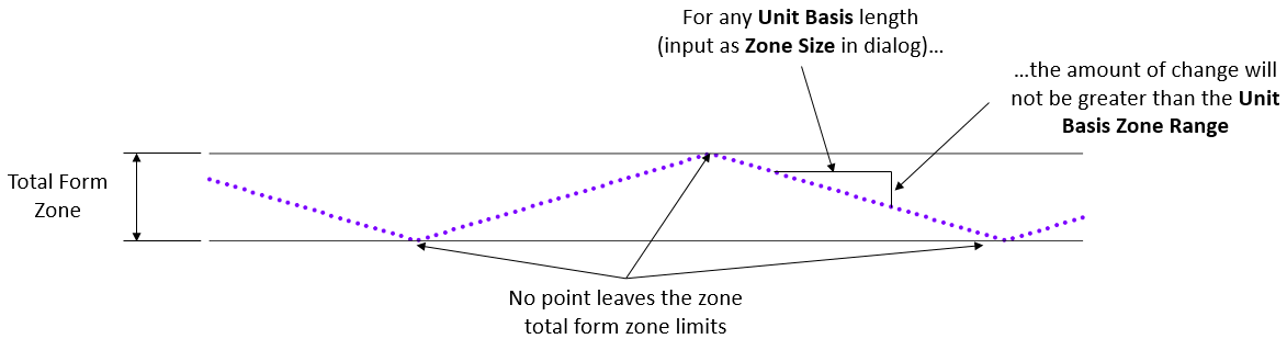
Technically using a Unit Basis in GD&T does not guarantee straight line bending as simulated here, however this is the easiest way to simulate this dependency when considering the complexity and number of points on a 2D or 3D feature.
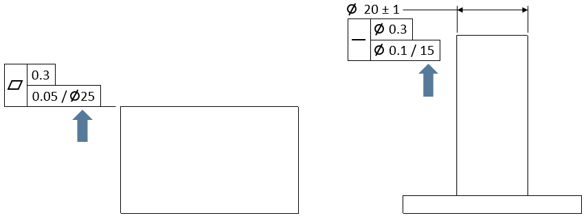
How 3DCS Uses the Zone Shape:
On a linear feature like the line of points shown above it is simple to think about how the Unit Basis Zone Size and Zone Shape could be used to determine what the Unit Basis length should be. However, when looking at a 2D feature it becomes a bit more complicated. Take an example where I have a square feature of size 50x50 and a Zone Shape of a 25x25 square. We would commonly think of this to be telling us that the Unit Basis length must be 25, however as is displayed in the image below, assuming a Unit Basis of 25 would actually over vary the form on this feature.
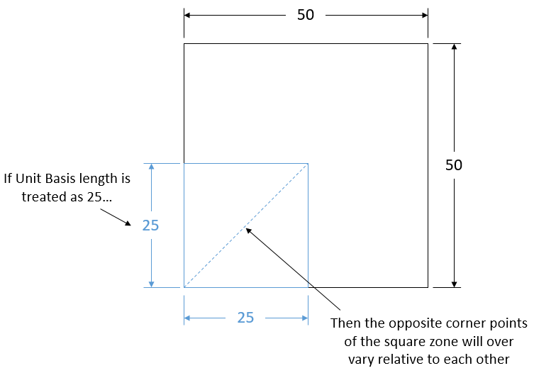
For this reason, the hypotenuse of the rectangular zone must be used as the Unit Basis length for any Rectangular Zone Shape. That way a rectangle can be placed anywhere and in any orientation on the face and 3DCS will have not violated the Unit Basis refinement of the form GD&T:
Unit-Rate-Radius = SQRT(L^2 + W^2) for Rectangular Zone
A Diameter Zone Shape is much simpler as there is only one number input. The Unit Basis length is simply the value entered for the Zone Size:
Unit-Rate-Radius = L for Diametrical Zone
Notes:oWhen measuring a point in a tolerance with Unit Basis (Rate of Change) and if the point has a Circle Size tolerance, no Contributor output will be shown of the Unit Basis deviation, in the measure results. But the measure will report the Unit Basis deviations in Monte Carlo analysis. (74211) oUnit Base is applied to Lines: when we add all lines to the same GD&T callout they are treated like a surface, while when they are in separate callouts they are treated like individual lines. oWhen the Unit Base is applied to Points or single Edges, they're treated as individual lines.
|