IV. Rigid Model Summary
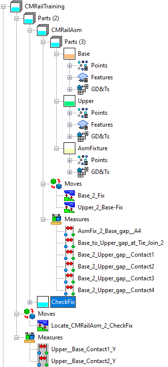
Completed model of a Rail Assembly consisting of Base, Upper, Assembly Fixture and Checking Fixture. Base and Upper parts are assembled on the Assembly Fixture, then transferred onto the Checking Fixture. Measurements are taken at each assembly level.
First open the model called CMRailTraining_Rigid

POINTS
All points that will be used in compliant moves are already in the model. There are extra points created on the parts used to approximate the part's deformation, based on their displacement. These points are linked to FEA mesh nodes and because their only purpose is to properly deform the part, they are hidden. For better visualization it is recommended that the linked modeling points will be evenly distributed over the surface of the part. Increasing the number of linked points will increase the deformation accuracy for the entire part.
MOVES
•CMRailAsm
1. Base_2_Fix (Step Plane) - Base part locates completely to Assembly Fixture, using Step Plane, a rigid body move.
2. Upper_2_Base-Fix (Step Plane) - Upper part locates to Base surface and Assembly Fixture pins, using Step Plane, a rigid body move.
•CMRailTraining (currently deactivated)
3.Locate_CMRailAsm_2_CheckFix (Step Plane) - Assembled Upper and Base locate completely to Checking Fixture, using Step Plane, a rigid body move.
TOLERANCES
•Base and Upper have 0.2mm size tolerance and 1.0mm surface profile tolerances
•Assembly Fixture has 0.1mm size tolerance on its pins and 5.0mm profile tolerance on its offset pad.
•Checking Fixture has 0.0mm size tolerance.
MEASURES
•CMRailAsm
AsmFix_2_Base_gap_A4 measures the fourth location point to the offset AsmFixture pad. This measure will be checked during the entire assembly process.
Base_to_Upper_gap_at_Tie_Join_2 measures the distance between the Base and Upper at the first pair of the Tie move.
Base_2_Upper_gap_Contact1 - 4 measure the gap at the four corners between Base and Upper.
•CMRailTraining (currently deactivated)
Upper__Base_Contact1_Y and Upper_Base_Contact2_Y measure the alignment in y-direction between the top flanges of the Base and Upper parts.
4.1. ![]() Nominal Build the model and using the DCS Navigation Tree, open the first measurement AsmFix_2_Base_gap_A4. Notice the Current value is 5.0mm. This gap occurs when the Base is treated as completely rigid. The current rigid body move locates the Base, using A1, A2, and A3. the gap is intentionally created at the fourth Base locator (A4), for demonstration purposes.
Nominal Build the model and using the DCS Navigation Tree, open the first measurement AsmFix_2_Base_gap_A4. Notice the Current value is 5.0mm. This gap occurs when the Base is treated as completely rigid. The current rigid body move locates the Base, using A1, A2, and A3. the gap is intentionally created at the fourth Base locator (A4), for demonstration purposes.
4.2 You can also use the ![]() Run Analysis, Simulation only function, to run one sample. Then scroll through the measurements to see the Nominal values.
Run Analysis, Simulation only function, to run one sample. Then scroll through the measurements to see the Nominal values.
4.3 Save the model as CMRailTraining
RESULTS
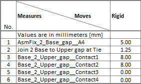
Below is a summary of the nominal values of the measurements, prior to any compliant modeling implementation.
