VI. Load FEA Data (Load_CM_data)
Requirements:
•Needs to be the first of the compliant moves in the Navigation tree.
•Loads the FEA information (input deck and stiffness matrix) for compliant parts.
•Can be created in parts or assemblies.
Things to know about Load FEA Data:
=> Once the mesh and stiffness files are selected, a Nominal Build is required to load the files and link modeling points to the selected set of mesh nodes.
6.1 Open the CMRailTrainingRigid.wtx CMRailTrainingRigid.CATProduct cmrailtraining_rigid.SLDASM cmrailtraining_rigid.asm CMRailTrainingRigid.prt CMRailTraining A.1.3dxml. Because the Base and Upper are compliant parts, the FEA Mesh and Stiffness Matrix, previously generated, must be loaded for both parts.
6.2 Select the ![]() Load FEA Data icon and choose CMRailAsm as parent part for the move.
Load FEA Data icon and choose CMRailAsm as parent part for the move.
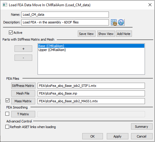
6.3 Name the move "Load_CM_data".
6.4 Select the ![]() Plus button from Parts with Stiffness Mtx and Mesh field and click on the Base.
Plus button from Parts with Stiffness Mtx and Mesh field and click on the Base.
Note: The software will automatically prompt for a Stiffness Matrix file selection (*.bdf, .pch* or *.mtx) and then an FEA Mesh file selection (*.nas, *.blk, or *.inp).
6.5 Select these files from the FEA folder under Compliant Model: dcsFea_abq_Base_job2_STIF1.mtx and dcsFea_abq_Base.inp.
6.6 Click on the ![]() Plus button and repeat the same process for the Upper part. Select these files: dcsFea_abq_Upper_job2_STIF1.mtx and dcsFea_abq_Upper.inp.
Plus button and repeat the same process for the Upper part. Select these files: dcsFea_abq_Upper_job2_STIF1.mtx and dcsFea_abq_Upper.inp.
6.7 Select the Mass Matrix files from the same folder for each part. Mass Matrix is needed to apply gravity on the parts.
>>> File path may vary<<<
6.8 Click [OK] to close the dialog box.
Step-by-step:
1. Open Load FEA Data dialog.
2. Select part.
3. Select matrices and mesh file.
6.9 ![]() Nominal Build to apply the move.
Nominal Build to apply the move.
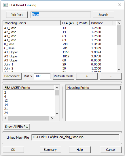
6.10 Click on the ![]() FEA Point Linking icon to open the CM Point Linking Wizard dialog box, and use the [Pick Part] button to select Base, if not selected already.
FEA Point Linking icon to open the CM Point Linking Wizard dialog box, and use the [Pick Part] button to select Base, if not selected already.
6.11 Use the [Pick Part] button to select the Upper and verify the points linking.
6.12 Select [OK] button to close the CM Point Linking Wizard dialog box.
Step-by-step:
1. Open FEA Point Linking dialog.
2. Select part.
3. Click on 'Distance' to reorder by smallest or largest distance between modeling point and mesh node.
4. Click Summary to see if there are any double links or unlinked points.
Things to know about CM Point Linking Wizard:
=> Shows the links between modeling points and mesh nodes and the distance between them.
=> Allows breaking links and relinking to different node if desired with the 'plus' and 'minus' buttons.
=> Allows breaking links to all nodes using the Refresh mesh button.
6.13 Save the model.
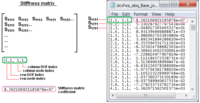
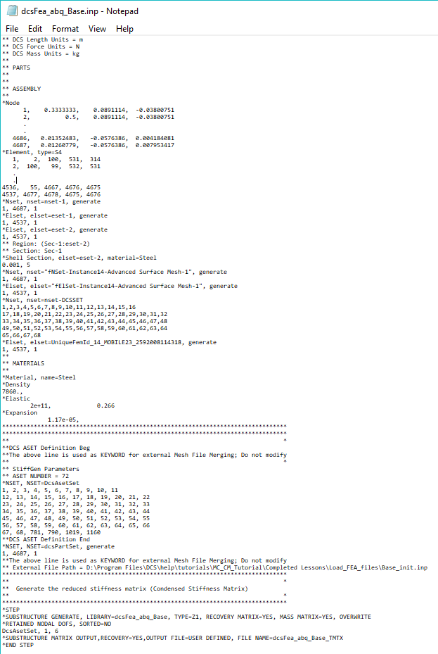
Example of FEA Mesh and Stiffness Matrix files for Base
• FEA Mesh Input deck(dcsFea_abq_Base.inp).
•Reduced Stiffness Matrix file (dcsFea_abq_Base_Job2_STIF1.mtx)